HP Indigo WS6600 Splice Detection System Installation and Troubleshooting -- C - Page 19
FI Pin 24, IBS1 Pin 24, V terminal block L+1 at bottom of electronics cabinet - red wire with label
 |
View all HP Indigo WS6600 manuals
Add to My Manuals
Save this manual to your list of manuals |
Page 19 highlights
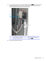
1. In the electronics cabinet, next to the PLC unit, mount the connector bracket (CA344-35920) using two M4 Allen screws. 2. Connect the molex connector of cable CA361-25080 to the bracket. Cable CA361-25080 has 5 wires emanating from the molex connector that connect to: ● Digitax FI pin 24 - white wire with label FI Pin 24 ● Digitax FP pin 27 - white wire with label FP Pin 27 ● Digitax IBS1 pin 24 - white wire with label IBS1 Pin 24 ● 24 V terminal block L+1 at bottom of electronics cabinet - red wire with label 24V ● 24 V terminal GND - black wire with label GND Installing the wiring 17
-
 1
1 -
2
-
3
-
4
-
5
-
6
-
7
-
8
-
9
-
10
-
11
-
12
-
13
-
 14
14 -
 15
15 -
 16
16 -
 17
17 -
 18
18 -
 19
19 -
 20
20 -
 21
21 -
 22
22 -
 23
23 -
 24
24 -
25
-
26
-
27
-
28
-
29
-
30
-
31
-
32
-
33
-
34
-
35
-
36
-
37
-
38
-
39
-
40
-
41
-
42
-
43
-
44
-
45
-
46
 |
 |

1.
In the electronics cabinet, next to the PLC unit, mount the connector bracket (CA344-35920) using
two M4 Allen screws.
2.
Connect the molex connector of cable CA361-25080 to the bracket.
Cable CA361-25080 has 5 wires emanating from the molex connector that connect to:
●
Digitax FI pin 24 — white wire with label
FI Pin 24
●
Digitax FP pin 27 — white wire with label
FP Pin 27
●
Digitax IBS1 pin 24 — white wire with label
IBS1 Pin 24
●
24 V terminal block L+1 at bottom of electronics cabinet — red wire with label
24V
●
24 V terminal GND — black wire with label
GND
Installing the wiring
17