HP Indigo WS6600 Splice Detection System Installation and Troubleshooting -- C - Page 37
Diagnostics variable p_Splice_um% in drive FP shows the position of the splice relative to the ITM
 |
View all HP Indigo WS6600 manuals
Add to My Manuals
Save this manual to your list of manuals |
Page 37 highlights
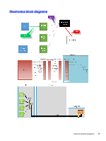
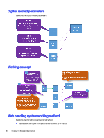
Direct digital input 24 VDC drive FP terminal 27; #19.34 = 0 (signal low), 1 (signal high) ● Splice sensor calibration signal from WHS to splice sensor: by FP Digitax Direct digital output 24 VDC drive FI terminal 24; #19.31 = 0 (signal low), 1 (signal high) ● Calibration success signal from splice sensor to WHS: by FP Digitax Direct digital input 24 VDC drive IBS1 terminal 24; #19.31 = 0 (signal low), 1 (signal high). This signal can be used additionally as web break signal. ● Splice stop option If the stop option is enabled, the splice is tracked up to the RW table. A diagnostics variable in drive FP shows the position of the splice relative to the RW table. This position is in micron units and it counts down towards 0 while the web is moving forward. Position 0 means that the leading edge of the splice area has reached the center of the RW table. ● Sensor calibration procedure The calibration signal to the sensor is set too high for a defined web distance to pass the sensor. The local FP drive parameter #20.01 defines the calibration being done. The calibration signal is set high after the web has started to move and the web speed is above the threshold (local FP drive parameter cv_WebMin_mm_s% = 50 mm/s). The signal stays high until a specific web distance has passed the sensor (local FP drive parameter c_TeachDistance_mm% = 2000 mm). The calibration signal is then set low for time ct_SpliceSensorTeachOff2% before calibration success is checked. Each calibration attempt waits for another 2000 mm of web to pass. There is a timeout for each calibration attempt. The timeout counter starts after the web has started to move (local parameter ct_SpliceDistanceTimeOut_ms% = 30000 ms = 30 sec). If the calibration attempt does not finish in time, either a new calibration attempt is started or if it is the last calibration attempt, the calibration fails. ● Splice position Diagnostics variable p_Splice_um% in drive FP shows the position of the splice relative to the ITM print nip. This position is in micron units and it counts down towards 0 while the web is moving forward. Position 0 means that the leading edge of the splice area has reached the print nip. ● Splice detection enable command The FP enable/disable of splice detection feature in WHS, bit: 0=splice detection disabled, 1=enabled ● Stop after splice skip command The FP enables/disables the option for web stopping after splice skipping. If enabled, splice should automatically stop on rewinder inspection table, bit: 0=splice stop at RW disabled, 1=enabled ● Web distance from ITM print nip to RW table The FP controls the web distance from ITM print nip to RW table when IBS2 is in "empty" position (default value: 6000). ● Splice sensor manual calibration command Web handling system working method 35
-
 1
1 -
2
-
3
-
4
-
5
-
6
-
7
-
8
-
9
-
10
-
11
-
12
-
13
-
14
-
15
-
16
-
17
-
18
-
19
-
20
-
21
-
22
-
23
-
24
-
25
-
26
-
27
-
28
-
29
-
30
-
31
-
 32
32 -
 33
33 -
 34
34 -
 35
35 -
 36
36 -
 37
37 -
 38
38 -
 39
39 -
 40
40 -
 41
41 -
 42
42 -
43
-
44
-
45
-
46
 |
 |
