HP Indigo WS6600 Splice Detection System Installation and Troubleshooting -- C - Page 24
Activating the splice detector
 |
View all HP Indigo WS6600 manuals
Add to My Manuals
Save this manual to your list of manuals |
Page 24 highlights
7. Using an M5 Allen screw, connect CA361-25050 cable's ground cable to the front holder bracket. 1 Cable CA361-25050 3 Cable CA361-25050 ground cable connected to front holder bracket 2 Cable CA361-25050 molex connector 8. Connect the cable CA361-25050 molex connector to the sensor cable molex connector that is installed on the front holder bracket. 1 Sensor cables and cable CA361-25050 3 Sensor molex connector arranged and tie-wrapped 2 Cable CA361-25050 molex connector Activating the splice detector Follow these steps to activate the splice detector. 1. Turn on the press. 2. Check that the LED on the long sensor turns ON (either green or red). 22 Chapter 2 Installation procedures
-
 1
1 -
2
-
3
-
4
-
5
-
6
-
7
-
8
-
9
-
10
-
11
-
12
-
13
-
14
-
15
-
16
-
17
-
18
-
 19
19 -
 20
20 -
 21
21 -
 22
22 -
 23
23 -
 24
24 -
 25
25 -
 26
26 -
 27
27 -
 28
28 -
 29
29 -
30
-
31
-
32
-
33
-
34
-
35
-
36
-
37
-
38
-
39
-
40
-
41
-
42
-
43
-
44
-
45
-
46
 |
 |

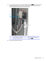
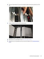
7.
Using an M5 Allen screw, connect CA361-25050 cable’s ground cable to the front holder bracket.
1
Cable CA361-25050
3
Cable CA361-25050 ground cable
connected to front holder bracket
2
Cable CA361-25050 molex connector
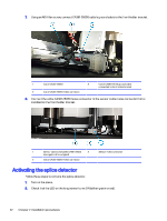
8.
Connect the cable CA361-25050 molex connector to the sensor cable molex connector that is
installed on the front holder bracket.
1
Sensor cables and cable CA361-25050
arranged and tie-wrapped
3
Sensor molex connector
2
Cable CA361-25050 molex connector
Activating the splice detector
Follow these steps to activate the splice detector.
1.
Turn on the press.
2.
Check that the LED on the long sensor turns ON (either green or red).
22
Chapter 2
Installation procedures