HP Indigo WS6600 Splice Detection System Installation and Troubleshooting -- C - Page 25
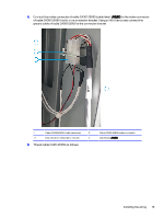
Reinstall the cover at the engine input side and close the bridge door. See
 |
View all HP Indigo WS6600 manuals
Add to My Manuals
Save this manual to your list of manuals |
Page 25 highlights
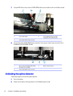
3. Place your finger between the sensors (to simulate threaded substrate) and verify that the LED is red. 4. Thread substrate through the sensor bracket opening. 5. Reinstall the cover at the bridge front. See Preliminary steps on page 4. 6. Reinstall the cover at the engine input side and close the bridge door. See Preliminary steps on page 4. Activating the splice detector 23
-
 1
1 -
2
-
3
-
4
-
5
-
6
-
7
-
8
-
9
-
10
-
11
-
12
-
13
-
14
-
15
-
16
-
17
-
18
-
19
-
 20
20 -
 21
21 -
 22
22 -
 23
23 -
 24
24 -
 25
25 -
 26
26 -
 27
27 -
 28
28 -
 29
29 -
 30
30 -
31
-
32
-
33
-
34
-
35
-
36
-
37
-
38
-
39
-
40
-
41
-
42
-
43
-
44
-
45
-
46
 |
 |

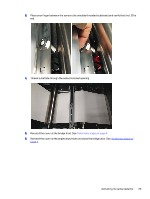
3.
Place your finger between the sensors (to simulate threaded substrate) and verify that the LED is
red.
4.
Thread substrate through the sensor bracket opening.
5.
Reinstall the cover at the bridge front. See
Preliminary steps
on page
4
.
6.
Reinstall the cover at the engine input side and close the bridge door. See
Preliminary steps
on
page
4
.
Activating the splice detector
23