HP J9146A Installation Guide - Page 15
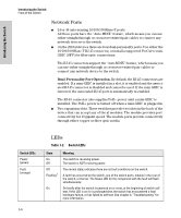
Introducing the Switch, Switch LEDs, State, Meaning, Link and Mode - specifications
 |
UPC - 884420766971
View all HP J9146A manuals
Add to My Manuals
Save this manual to your list of manuals |
Page 15 highlights
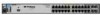
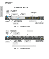
Introducing the Switch Introducing the Switch Front of the Switch Switch LEDs Locator (Blue) Test (green/orange) Port LEDs (green/orange - Link and Mode) LED Mode View (green LEDs) Mdl (Module Status, green) State On Flashing Off Off On green Flashing orange1 Link Mode Act FDx Spd PoE Usr On Flashing Off Meaning The Locator LED is used to locate a specific chassis in a area full of chassis. The LED can be set to be on solid or flash for a specified number of minutes (1-1440). The default is 30 minutes. Use the command "chassislocate". The normal operational state; the switch is not undergoing self test. The switch self test and initialization are in progress after the switch has been power cycled or reset. The switch is not operational until this LED goes off. The Self Test LED also comes on briefly when you "hot swap" a mini-GBIC into the switch; the mini-GBIC is self tested when it is hot swapped. A component of the switch has failed its self test. The status LED for that component, for example an RJ-45 port, and the switch Fault LED will flash simultaneously. Indicates the port LEDs are displaying link information: • if the port LED is on, the port is enabled and receiving a link indication from the connected device. • if the port LED is off, the port has no active network cable connected, or is not receiving link beat or sufficient light. Otherwise, the port may have been disabled through the switch console, the web browser interface, or ProCurve Manager. if the port LED is Flashing1 (orange) simultaneously with the Fault LED, the corresponding port has failed its self test. The operation of the Mode LED is controlled by the LED Mode select button, and the current setting is indicated by the LED Mode indicator LEDs near the button. Press the button to step from one view mode to the next. The default view is Activity (Act). Indicates the port LEDs are displaying network activity information. Indicates port LEDs are lit for ports in Full Duplex Mode. Off indicates ½ duplex. Indicates the port LEDs are displaying the connection speed at which each port is operating: • if the port LED is off, the port is operating at 10 Mbps. • if the port LED is Flashing**, the port is operating at 100 Mbps. • if the port LED is on continuously, the port is operating at 1000 Mbps. • If the Mode LED is on the port is providing PoE power. • If the Mode LED is off the port is not providing PoE power. • If the Link LED is on the port is enabled for PoE. • If the Link LED is off the port is disabled for PoE. • If the Link LED is Flashing, the port has an error or the port is denied power due to insufficient power. Reserved for future development Expansion module is plugged into expansion slot and operating correctly Expansion module is plugged into expansion slot but has experienced a fault Expansion module is not plugged into expansion slot 1-7
-
 1
1 -
2
-
3
-
4
-
5
-
6
-
7
-
8
-
9
-
 10
10 -
 11
11 -
 12
12 -
 13
13 -
 14
14 -
 15
15 -
 16
16 -
 17
17 -
 18
18 -
 19
19 -
 20
20 -
21
-
22
-
23
-
24
-
25
-
26
-
27
-
28
-
29
-
30
-
31
-
32
-
33
-
34
-
35
-
36
-
37
-
38
-
39
-
40
-
41
-
42
-
43
-
44
-
45
-
46
-
47
-
48
-
49
-
50
-
51
-
52
-
53
-
54
-
55
-
56
-
57
-
58
-
59
-
60
-
61
-
62
-
63
-
64
-
65
-
66
-
67
-
68
-
69
-
70
-
71
-
72
-
73
-
74
-
75
-
76
-
77
-
78
-
79
-
80
-
81
-
82
-
83
-
84
-
85
-
86
-
87
-
88
-
89
-
90
-
91
-
92
-
93
-
94
-
95
-
96
-
97
-
98
-
99
-
100
-
101
-
102
-
103
-
104
-
105
-
106
-
107
-
108
-
109
-
110
-
111
-
112
-
113
-
114
-
115
-
116
 |
 |
