HP J9146A Installation Guide - Page 68
Diagnosing with the LEDs, Troubleshooting, Table 4-1., LED Error Indicators
 |
UPC - 884420766971
View all HP J9146A manuals
Add to My Manuals
Save this manual to your list of manuals |
Page 68 highlights
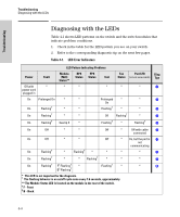
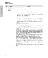
Troubleshooting Troubleshooting Diagnosing with the LEDs Diagnosing with the LEDs Table 4-1 shows LED patterns on the switch and the switch modules that indicate problem conditions. 1. Check in the table for the LED pattern you see on your switch. 2. Refer to the corresponding diagnostic tip on the next few pages. Table 4-1. LED Error Indicators LED Pattern Indicating Problems Power Fault Module RPS EPS Fan Port LED Diag (Mdl) Status Status Test Status (in Link view mode) Tips Status** Off with * power cord plugged in * * * * * ➊ On Prolonged On * * On Flashing† * * On Flashing† * * On Flashing† See tip 5 * Prolonged * On * ➋ Flashing† * * ➌ Off Flashing† * ➍ Flashing† * Flashing† ➎ On Off * * Off * Off with cable ➏ connected On Off * * Off * On, but the port is ➐ not communicating On Flashing† * Flashing† * * * * ➑ On Flashing† * * Flashing† * * * ➒ On Flashing† F1 Flashing† * B2 Flashing† Flashing† * * ➓ * This LED is not important for the diagnosis. † The flashing behavior is an on/off cycle once every 1.6 seconds, approximately. ** The Module Status LED is located on the module in the rear of the switch. 1 F - Front 2 B - Back 4-4
-
 1
1 -
2
-
3
-
4
-
5
-
6
-
7
-
8
-
9
-
10
-
11
-
12
-
13
-
14
-
15
-
16
-
17
-
18
-
19
-
20
-
21
-
22
-
23
-
24
-
25
-
26
-
27
-
28
-
29
-
30
-
31
-
32
-
33
-
34
-
35
-
36
-
37
-
38
-
39
-
40
-
41
-
42
-
43
-
44
-
45
-
46
-
47
-
48
-
49
-
50
-
51
-
52
-
53
-
54
-
55
-
56
-
57
-
58
-
59
-
60
-
61
-
62
-
 63
63 -
 64
64 -
 65
65 -
 66
66 -
 67
67 -
 68
68 -
 69
69 -
 70
70 -
 71
71 -
 72
72 -
 73
73 -
74
-
75
-
76
-
77
-
78
-
79
-
80
-
81
-
82
-
83
-
84
-
85
-
86
-
87
-
88
-
89
-
90
-
91
-
92
-
93
-
94
-
95
-
96
-
97
-
98
-
99
-
100
-
101
-
102
-
103
-
104
-
105
-
106
-
107
-
108
-
109
-
110
-
111
-
112
-
113
-
114
-
115
-
116
 |
 |
