HP J9146A Installation Guide - Page 45
Operating Characteristics of the 620 RPS/EPS (J8696A), Installing the Switch, - switch manual
 |
UPC - 884420766971
View all HP J9146A manuals
Add to My Manuals
Save this manual to your list of manuals |
Page 45 highlights
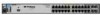
Installing the Switch Installing the Switch Installation Procedures These external power supplies support hot plugging of the RPS cable without causing a reboot of the switch or causing the power supply in either of the power supplies, or switch to shut down temporarily or permanently. For more information refer to the documentation for the external power supplies located on the ProCurve Web site at www.hp.com/go/procurve/manuals. Operating Characteristics of the 620 RPS/EPS (J8696A) The 620 RPS/EPS has two RPS ports, each of which can provide redundant +12V power to a connected switch. If a switch with no AC power is connected to an operating 620 RPS/EPS, the switch will not power on. For the switch to receive power from the external power supply, the switch must first be powered up then connected to the external power supply. For redundant AC power, connect the 620 RPS/EPS to the switch using one of the supplied RPS cables. RPS cables are 2 meters (6.56 feet) in length. The 620 RPS/EPS also has two EPS Ports which can not be used with the 2910al Switches. 620 RPS/EPS LEDs The 620 RPS/EPS LEDs are located on the front and back of the device. The following illustration shows an example of the back of the 620 RPS/EPS. There are two dual colored (green/orange) LEDs for each RPS and EPS port: ■ Device Connected ■ Power Status RPS port LEDs EPS port LEDs RPS ports Figure 2-15. Back of 620 RPS/EPS EPS ports, not used 2-19
-
 1
1 -
2
-
3
-
4
-
5
-
6
-
7
-
8
-
9
-
10
-
11
-
12
-
13
-
14
-
15
-
16
-
17
-
18
-
19
-
20
-
21
-
22
-
23
-
24
-
25
-
26
-
27
-
28
-
29
-
30
-
31
-
32
-
33
-
34
-
35
-
36
-
37
-
38
-
39
-
 40
40 -
 41
41 -
 42
42 -
 43
43 -
 44
44 -
 45
45 -
 46
46 -
 47
47 -
 48
48 -
 49
49 -
 50
50 -
51
-
52
-
53
-
54
-
55
-
56
-
57
-
58
-
59
-
60
-
61
-
62
-
63
-
64
-
65
-
66
-
67
-
68
-
69
-
70
-
71
-
72
-
73
-
74
-
75
-
76
-
77
-
78
-
79
-
80
-
81
-
82
-
83
-
84
-
85
-
86
-
87
-
88
-
89
-
90
-
91
-
92
-
93
-
94
-
95
-
96
-
97
-
98
-
99
-
100
-
101
-
102
-
103
-
104
-
105
-
106
-
107
-
108
-
109
-
110
-
111
-
112
-
113
-
114
-
115
-
116
 |
 |
