HP J9146A Installation Guide - Page 33
LED Behavior: - - poe switch
 |
UPC - 884420766971
View all HP J9146A manuals
Add to My Manuals
Save this manual to your list of manuals |
Page 33 highlights
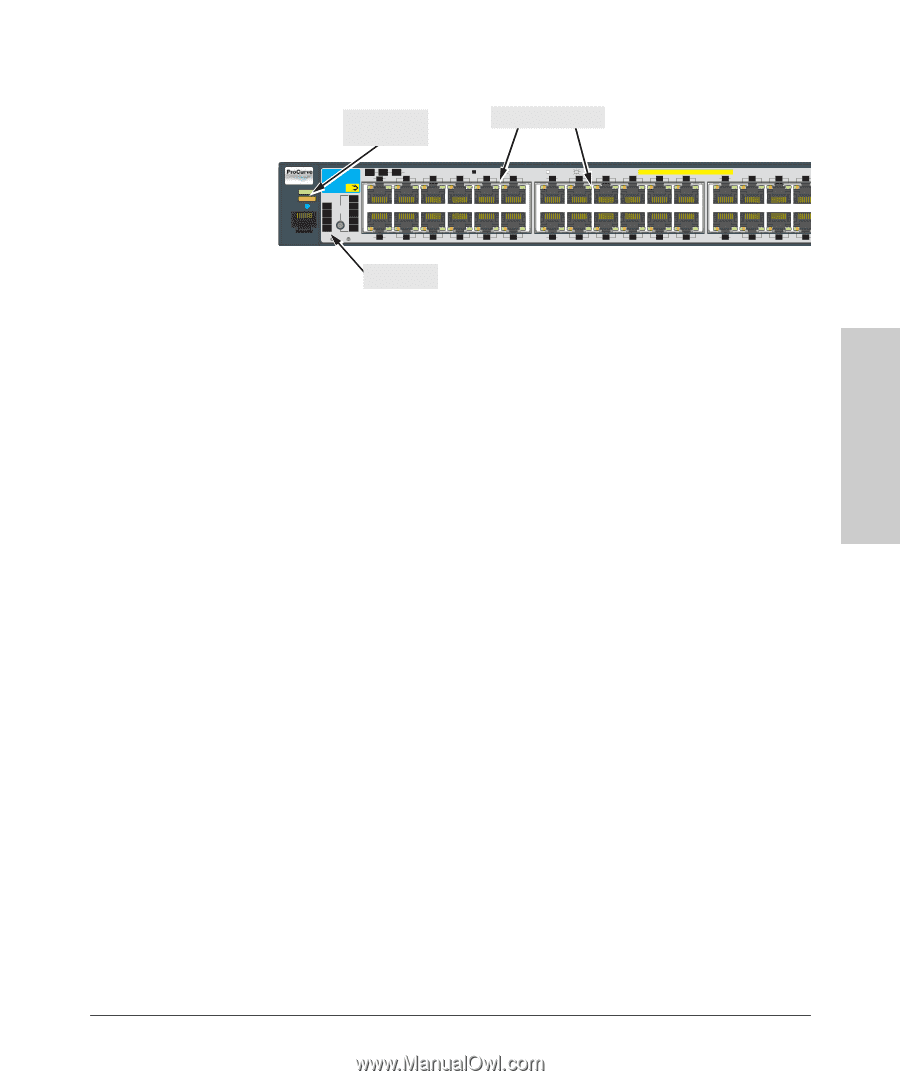
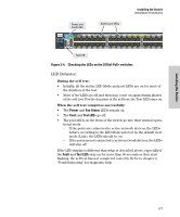
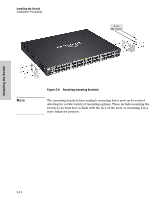
Installing the Switch Installing the Switch Installation Procedures Power and Fault LEDs Switch port LEDs * ProCurve Switch Mdl EPS RPS Status of the Back Spd mode: off=10 Mbps, 2 flash=100 Mbps, on=1 Gbps, 3 flash=10 Gbps PoE+ Integrated 10/100/1000Base-T Ports (1 - 48T) — Ports are Auto-MDIX 2910bl-48G-PoE Link 1 Mode 3 5 7 9 11 Link 13 Mode 15 17 19 21 23 Link 25 Mode 27 29 31 Power J9148A PoE+ Fault Locator Status PoE LED Tmp Mode Act FDx Spd * Fan PoE Test Usr Console Reset Clear Link 2 Mode 4 6 8 10 12 Link 14 Mode 16 18 20 22 24 Link 26 Mode 28 30 32 Test LED Figure 2-4. Checking the LEDs on the 2910al-PoE+ switches LED Behavior: During the self test: • Initially, all the status, LED Mode and port LEDs are on for most of the duration of the test. • Most of the LEDs go off and then may come on again during phases of the self test. For the duration of the self test, the Test LED stays on. When the self test completes successfully: • The Power and Fan Status LEDs remain on. • The Fault and Test LEDs go off. • The port LEDs on the front of the switch go into their normal opera- tional mode: - If the ports are connected to active network devices, the LEDs behave according to the LED Mode selected. In the default view mode (Link), the LEDs should be on. - If the ports are not connected to active network devices, the LEDs will stay off. If the LED display is different than what is described above, especially if the Fault and Test LEDs stay on for more than 60 seconds or they start flashing, the self test has not completed correctly. Refer to chapter 4, "Troubleshooting" for diagnostic help. 2-7
-
 1
1 -
2
-
3
-
4
-
5
-
6
-
7
-
8
-
9
-
10
-
11
-
12
-
13
-
14
-
15
-
16
-
17
-
18
-
19
-
20
-
21
-
22
-
23
-
24
-
25
-
26
-
27
-
 28
28 -
 29
29 -
 30
30 -
 31
31 -
 32
32 -
 33
33 -
 34
34 -
 35
35 -
 36
36 -
 37
37 -
 38
38 -
39
-
40
-
41
-
42
-
43
-
44
-
45
-
46
-
47
-
48
-
49
-
50
-
51
-
52
-
53
-
54
-
55
-
56
-
57
-
58
-
59
-
60
-
61
-
62
-
63
-
64
-
65
-
66
-
67
-
68
-
69
-
70
-
71
-
72
-
73
-
74
-
75
-
76
-
77
-
78
-
79
-
80
-
81
-
82
-
83
-
84
-
85
-
86
-
87
-
88
-
89
-
90
-
91
-
92
-
93
-
94
-
95
-
96
-
97
-
98
-
99
-
100
-
101
-
102
-
103
-
104
-
105
-
106
-
107
-
108
-
109
-
110
-
111
-
112
-
113
-
114
-
115
-
116
 |
 |