HP J9146A Installation Guide - Page 52
Console Cable Pinouts, RJ-45 to DB-9 pinouts, Table 2-3., Mapping of RJ-45 to DB-9 - procurve manual
 |
UPC - 884420766971
View all HP J9146A manuals
Add to My Manuals
Save this manual to your list of manuals |
Page 52 highlights
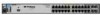
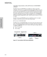
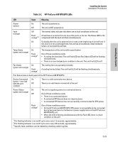
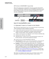
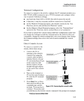
Installing the Switch Installation Procedures If you want to continue with console management of the switch at this time, see chapter 3, "Getting Started With Switch Configuration" for some basic configuration steps. For more detailed information, refer to the Management and Configuration Guide, which is on the ProCurve Website at www.hp.com/ go/procurve/manuals. Console Cable Pinouts The console cable has an RJ-45 plug on one end and a DB-9 female connector on the other end. Table 2-19 describes the mapping of the RJ-45 to DB-9 pins. 5 4 3 21 12345678 98 76 12345678 Installing the Switch Figure 2-20. RJ-45 to DB-9 pinouts Table 2-3. Mapping of RJ-45 to DB-9 RJ-45 (Signal reference from DB-9 (Signal reference from PC) Chassis Reserved 1 8 CTS Reserved 2 6 DSR TXD 3 2 RXD Reserved 4 1 DCD GND 5 5 GND RXD 6 3 TXD Reserved 7 4 DTR Reserved 8 7 RTS 9 RI 2-26
-
 1
1 -
2
-
3
-
4
-
5
-
6
-
7
-
8
-
9
-
10
-
11
-
12
-
13
-
14
-
15
-
16
-
17
-
18
-
19
-
20
-
21
-
22
-
23
-
24
-
25
-
26
-
27
-
28
-
29
-
30
-
31
-
32
-
33
-
34
-
35
-
36
-
37
-
38
-
39
-
40
-
41
-
42
-
43
-
44
-
45
-
46
-
 47
47 -
 48
48 -
 49
49 -
 50
50 -
 51
51 -
 52
52 -
 53
53 -
 54
54 -
 55
55 -
 56
56 -
 57
57 -
58
-
59
-
60
-
61
-
62
-
63
-
64
-
65
-
66
-
67
-
68
-
69
-
70
-
71
-
72
-
73
-
74
-
75
-
76
-
77
-
78
-
79
-
80
-
81
-
82
-
83
-
84
-
85
-
86
-
87
-
88
-
89
-
90
-
91
-
92
-
93
-
94
-
95
-
96
-
97
-
98
-
99
-
100
-
101
-
102
-
103
-
104
-
105
-
106
-
107
-
108
-
109
-
110
-
111
-
112
-
113
-
114
-
115
-
116
 |
 |
