HP J9146A Installation Guide - Page 30
Installation Procedures, Summary
 |
UPC - 884420766971
View all HP J9146A manuals
Add to My Manuals
Save this manual to your list of manuals |
Page 30 highlights
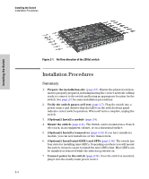
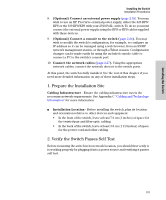
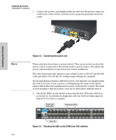
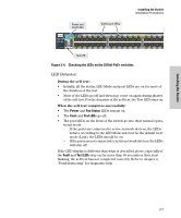
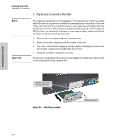
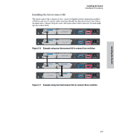
Installing the Switch Installing the Switch Installation Procedures Figure 2-1. Air flow direction of the 2910al switch Installation Procedures Summary 1. Prepare the installation site (page 2-5). Ensure the physical environment is properly prepared, including having the correct network cabling ready to connect to the switch and having an appropriate location for the switch. See page 2-3 for some installation precautions. 2. Verify the switch passes self test (page 2-5). Plug the switch into a power source and observe that the LEDs on the switch's front panel indicate correct switch operation. When self test is complete, unplug the switch. 3. (Optional) Install a module (page 2-8). 4. Mount the switch (page 2-11). The Switch can be mounted in a 19-inch telco rack, in an equipment cabinet, or on a horizontal surface. 5. (Optional) Install a transceiver (page 2-14). If you have installed a module, you can now install one or two transceivers. 6. (Optional) Install mini-GBICs and SFPs (page 2-16). The switch has four slots for installing mini-GBICs. Depending on where you will mount the switch, it may be easier to install the mini-GBICs first. Mini-GBICs can be installed or removed while the switch is powered on. 7. Connect power to the switch (page 2-18). Once the switch is mounted, plug it into the nearby main power source. 2-4
-
 1
1 -
2
-
3
-
4
-
5
-
6
-
7
-
8
-
9
-
10
-
11
-
12
-
13
-
14
-
15
-
16
-
17
-
18
-
19
-
20
-
21
-
22
-
23
-
24
-
 25
25 -
 26
26 -
 27
27 -
 28
28 -
 29
29 -
 30
30 -
 31
31 -
 32
32 -
 33
33 -
 34
34 -
 35
35 -
36
-
37
-
38
-
39
-
40
-
41
-
42
-
43
-
44
-
45
-
46
-
47
-
48
-
49
-
50
-
51
-
52
-
53
-
54
-
55
-
56
-
57
-
58
-
59
-
60
-
61
-
62
-
63
-
64
-
65
-
66
-
67
-
68
-
69
-
70
-
71
-
72
-
73
-
74
-
75
-
76
-
77
-
78
-
79
-
80
-
81
-
82
-
83
-
84
-
85
-
86
-
87
-
88
-
89
-
90
-
91
-
92
-
93
-
94
-
95
-
96
-
97
-
98
-
99
-
100
-
101
-
102
-
103
-
104
-
105
-
106
-
107
-
108
-
109
-
110
-
111
-
112
-
113
-
114
-
115
-
116
 |
 |
