HP J9146A Installation Guide - Page 37
Mount the Switch, Rack or Cabinet Mounting
 |
UPC - 884420766971
View all HP J9146A manuals
Add to My Manuals
Save this manual to your list of manuals |
Page 37 highlights
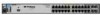
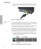
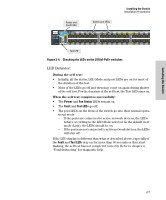
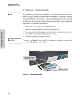
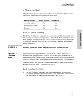
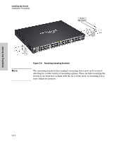
Installing the Switch WARNING Equipment Cabinet Note Installing the Switch Installation Procedures 4. Mount the Switch After the switch passes self test, it is ready to be mounted in a stable location. The 2910al Switches can be mounted in these ways: Mounting Location In a rack or cabinet On a horizontal surface On a wall Non-PoE Switches Yes Yes No PoE Switches Yes Yes No Rack or Cabinet Mounting The 2910al Switches are designed to be mounted in any EIA-standard 19-inch telco rack or communication equipment cabinet. Note the mounting brackets have multiple mounting holes and can be rotated allowing for a wide variety of mounting options. Secure the rack in accordance with the manufacture's safety guidelines. For safe operation, please read the mounting precautions on page 2-3, before mounting a switch. The 12-24 screws supplied with the switch are the correct threading for standard EIA/TIA open 19-inch racks. If you are installing the switch in an equipment cabinet such as a server cabinet, use the clips and screws that came with the cabinet in place of the 12-24 screws that are supplied with the switch. Complete step 1, and plan which four holes you will be using in the cabinet and install all four clips. Then proceed to step 2. Rack Mounting the Switch 1. Use a #1 Phillips (cross-head) screwdriver and attach the mounting brackets to the switch with the included 8-mm M4 screws. Remember to use the correct accessory kit for your switch, see page 2-1. 2-11
-
 1
1 -
2
-
3
-
4
-
5
-
6
-
7
-
8
-
9
-
10
-
11
-
12
-
13
-
14
-
15
-
16
-
17
-
18
-
19
-
20
-
21
-
22
-
23
-
24
-
25
-
26
-
27
-
28
-
29
-
30
-
31
-
 32
32 -
 33
33 -
 34
34 -
 35
35 -
 36
36 -
 37
37 -
 38
38 -
 39
39 -
 40
40 -
 41
41 -
 42
42 -
43
-
44
-
45
-
46
-
47
-
48
-
49
-
50
-
51
-
52
-
53
-
54
-
55
-
56
-
57
-
58
-
59
-
60
-
61
-
62
-
63
-
64
-
65
-
66
-
67
-
68
-
69
-
70
-
71
-
72
-
73
-
74
-
75
-
76
-
77
-
78
-
79
-
80
-
81
-
82
-
83
-
84
-
85
-
86
-
87
-
88
-
89
-
90
-
91
-
92
-
93
-
94
-
95
-
96
-
97
-
98
-
99
-
100
-
101
-
102
-
103
-
104
-
105
-
106
-
107
-
108
-
109
-
110
-
111
-
112
-
113
-
114
-
115
-
116
 |
 |
