HP LaserJet Pro 100 Service Manual - Page 83
Reinstallation tip, Remove the low-voltage power supply assembly 5 of 9
 |
View all HP LaserJet Pro 100 manuals
Add to My Manuals
Save this manual to your list of manuals |
Page 83 highlights
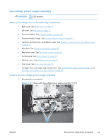
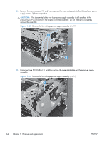
4. Release one cable from the cable guide (callout 1), and then remove two screws (callout 2). Figure 1-84 Remove the low-voltage power supply assembly (4 of 9) 2 1 5. Remove the power receptacle (callout 1) and guide (callout 2) as an assembly. Reinstallation tip Make sure that these parts are correctly assembled, before reinstalling the receptacle and guide. See Reinstall the low-voltage power supply on page 68. Figure 1-85 Remove the low-voltage power supply assembly (5 of 9) 2 1 ENWW Removal and replacement procedures 65
-
 1
1 -
2
-
3
-
4
-
5
-
6
-
7
-
8
-
9
-
10
-
11
-
12
-
13
-
14
-
15
-
16
-
17
-
18
-
19
-
20
-
21
-
22
-
23
-
24
-
25
-
26
-
27
-
28
-
29
-
30
-
31
-
32
-
33
-
34
-
35
-
36
-
37
-
38
-
39
-
40
-
41
-
42
-
43
-
44
-
45
-
46
-
47
-
48
-
49
-
50
-
51
-
52
-
53
-
54
-
55
-
56
-
57
-
58
-
59
-
60
-
61
-
62
-
63
-
64
-
65
-
66
-
67
-
68
-
69
-
70
-
71
-
72
-
73
-
74
-
75
-
76
-
77
-
 78
78 -
 79
79 -
 80
80 -
 81
81 -
 82
82 -
 83
83 -
 84
84 -
 85
85 -
 86
86 -
 87
87 -
 88
88 -
89
-
90
-
91
-
92
-
93
-
94
-
95
-
96
-
97
-
98
-
99
-
100
-
101
-
102
-
103
-
104
-
105
-
106
-
107
-
108
-
109
-
110
-
111
-
112
-
113
-
114
-
115
-
116
-
117
-
118
-
119
-
120
-
121
-
122
-
123
-
124
-
125
-
126
-
127
-
128
-
129
-
130
-
131
-
132
-
133
-
134
-
135
-
136
-
137
-
138
-
139
-
140
-
141
-
142
-
143
-
144
-
145
-
146
-
147
-
148
-
149
-
150
-
151
-
152
-
153
-
154
-
155
-
156
-
157
-
158
-
159
-
160
-
161
-
162
-
163
-
164
-
165
-
166
-
167
-
168
-
169
-
170
 |
 |
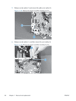
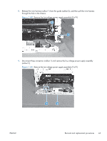
4.
Release one cable from the cable guide (callout 1), and then remove two screws (callout 2).
Figure 1-84
Remove the low-voltage power supply assembly (4 of 9)
1
2
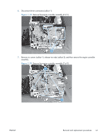
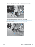
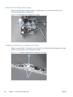
5.
Remove the power receptacle (callout 1) and guide (callout 2) as an assembly.
Reinstallation tip
Make sure that these parts are correctly assembled, before reinstalling the
receptacle and guide. See
Reinstall the low-voltage power supply
on page
68
.
Figure 1-85
Remove the low-voltage power supply assembly (5 of 9)
1
2
ENWW
Removal and replacement procedures
65