HP Management LAN Blade for bh7800 Installation Guide, Second Edition - HP Car - Page 18
Blade Server Cooling System
 |
View all HP Management LAN Blade for bh7800 manuals
Add to My Manuals
Save this manual to your list of manuals |
Page 18 highlights
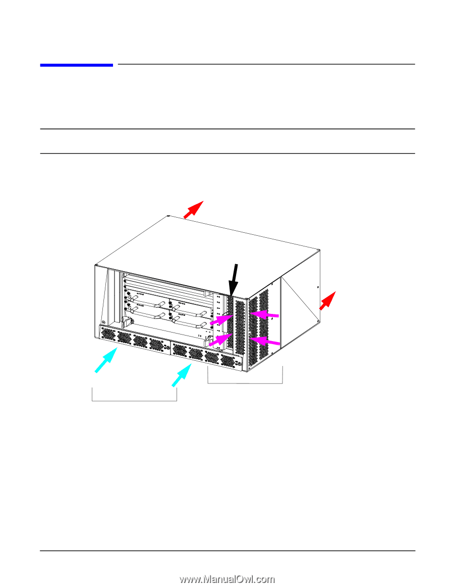
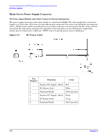
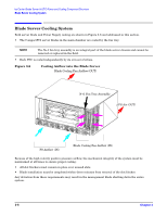
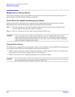
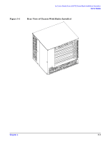
hp Carrier Grade Server bh3710 Power and Cooling Component Overview Blade Server Cooling System Blade Server Cooling System Both server blade and Power Supply cooling are shown in Figure 3-6 and addressed in this section. • The CompactPCI server blades in the main chamber are cooled by the fan tray. NOTE The N+1 fan tray assembly is an integral part of the blade server chassis and cannot be removed or replaced in the field. • Each PSU is cooled independently by its own set of 4 fans. Figure 3-6 Cooling Airflow into the Blade Server Blade Cooling Fan Airflow (OUT) N+1 Fan Tray Assembly PS Air (OUT) PS Airflow (IN) Blade Cooling Fan Airflow (IN) Because of the high velocity positive pressure airflow, the mechanical integrity of the system must be maintained at all times to ensure proper cooling: • All slot blockers must remain in place over unused slots. • Blade installation must be completed within three minutes from removal of the slot blocker. Any deviation from these requirements may result in the management blade shutting down the entire system. 3-6 Chapter 3
-
 1
1 -
2
-
3
-
4
-
5
-
6
-
7
-
8
-
9
-
10
-
11
-
12
-
 13
13 -
 14
14 -
 15
15 -
 16
16 -
 17
17 -
 18
18 -
 19
19 -
 20
20 -
 21
21 -
 22
22 -
 23
23 -
24
-
25
-
26
-
27
-
28
-
29
-
30
-
31
-
32
-
33
-
34
-
35
-
36
-
37
-
38
-
39
-
40
-
41
-
42
-
43
-
44
-
45
-
46
-
47
-
48
-
49
-
50
-
51
-
52
-
53
-
54
-
55
 |
 |