HP Management LAN Blade for bh7800 Installation Guide, Second Edition - HP Car - Page 36
bh3710 Chassis Rear View
 |
View all HP Management LAN Blade for bh7800 manuals
Add to My Manuals
Save this manual to your list of manuals |
Page 36 highlights
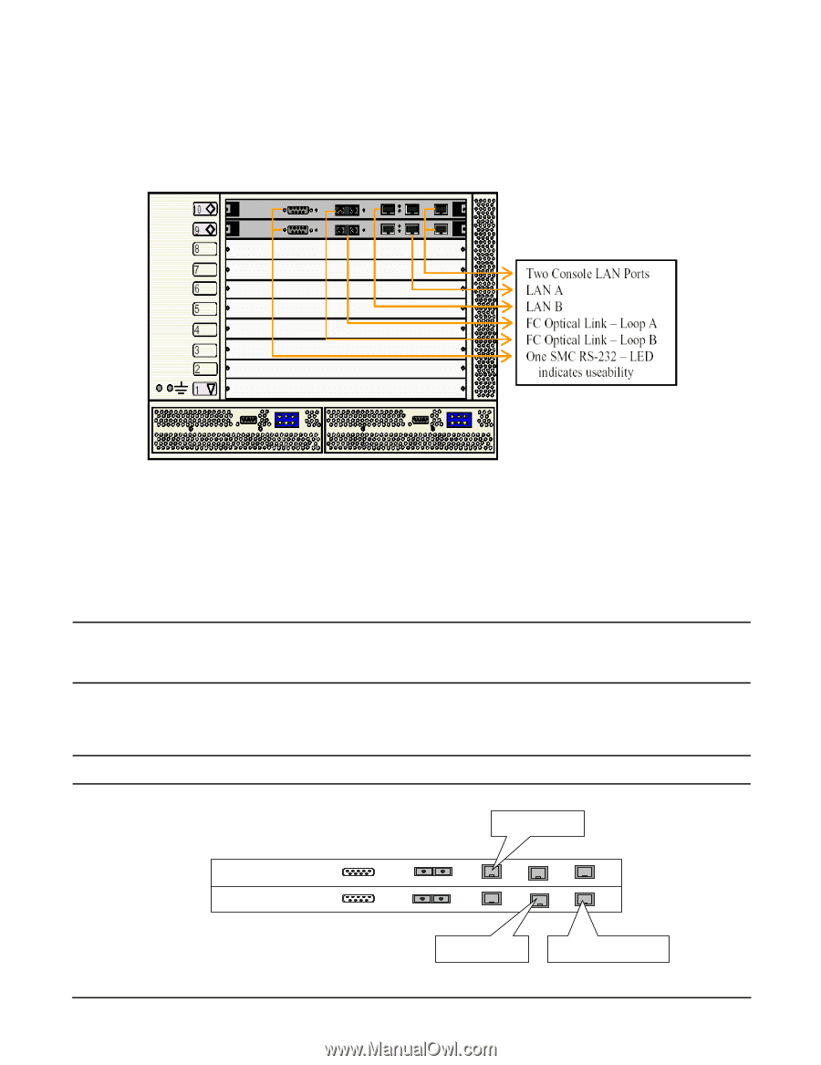
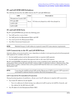
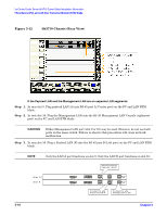
hp Carrier Grade Server bh3710 Server Blade Installation Information Fibrechannel (FC) and LAN Rear Transition Module (RTM) Blade Figure 5-12 bh3710 Chassis (Rear View) If the Payload LAN and the Management LAN are on separate LAN segments: Step 1. In rear slot 9: Plug payload LAN (A) into RJ-45 port A (Center port) on the FC and LAN RTM blade. Step 2. In rear slot 10: Plug the Management LAN into the RJ-45 Management LAN Console (rightmost port) on the FC and LAN RTM blade. CAUTION Either Management LAN port (slot 9 or 10) may be used. However, do not use both ports on the same switch. Failure to observe this precaution will cause network malfunction. Step 3. In rear slot 10: Plug a Payload LAN (B) into the RJ-45 port B (Left port) on the FC and LAN RTM blade. NOTE Only the LAN A port functions on slot 9. Only the LAN B port functions on slot 10. S lo t 1 0 S lo t 9 S erial S erial C o n n ect to s ite P ay lo a d L A N -B FC Loop B FC Loop A LAN B LAN B LAN A LAN A M gmt LAN M gmt LAN C o n n ec t to s ite P ay lo a d L A N -A C o nn e ct to site M anagem ent LAN 5- 16 Chapter 5
-
 1
1 -
2
-
3
-
4
-
5
-
6
-
7
-
8
-
9
-
10
-
11
-
12
-
13
-
14
-
15
-
16
-
17
-
18
-
19
-
20
-
21
-
22
-
23
-
24
-
25
-
26
-
27
-
28
-
29
-
30
-
 31
31 -
 32
32 -
 33
33 -
 34
34 -
 35
35 -
 36
36 -
 37
37 -
 38
38 -
 39
39 -
 40
40 -
 41
41 -
42
-
43
-
44
-
45
-
46
-
47
-
48
-
49
-
50
-
51
-
52
-
53
-
54
-
55
 |
 |