HP Management LAN Blade for bh7800 Installation Guide, Second Edition - HP Car - Page 45
Loosen Locking Screws, Releasing Locking Levers
 |
View all HP Management LAN Blade for bh7800 manuals
Add to My Manuals
Save this manual to your list of manuals |
Page 45 highlights
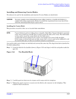
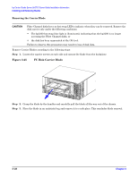
hp Carrier Grade Server bh3710 Server Blade Installation Information Installing and Removing Blades Figure 5-21 Loosen Locking Screws Step 3. To release the blade from the backplane, apply pressure to the left locking lever and to the right locking lever at the same time. You should be able to "snap" the levers away from each other and unlatch the blade from the left and right edges of the blade slot. Figure 5-22 illustrates this step. Figure 5-22 Releasing Locking Levers Chapter 5 5-25
-
 1
1 -
2
-
3
-
4
-
5
-
6
-
7
-
8
-
9
-
10
-
11
-
12
-
13
-
14
-
15
-
16
-
17
-
18
-
19
-
20
-
21
-
22
-
23
-
24
-
25
-
26
-
27
-
28
-
29
-
30
-
31
-
32
-
33
-
34
-
35
-
36
-
37
-
38
-
39
-
 40
40 -
 41
41 -
 42
42 -
 43
43 -
 44
44 -
 45
45 -
 46
46 -
 47
47 -
 48
48 -
 49
49 -
 50
50 -
51
-
52
-
53
-
54
-
55
 |
 |
Chapter 5
hp Carrier Grade Server bh3710 Server Blade Installation Information
Installing and Removing Blades
5-25
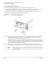
Figure 5-21
Loosen Locking Screws
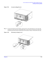
Step 3.
To release the blade from the backplane, apply pressure to the left locking lever and to the right
locking lever at the same time. You should be able to “snap” the levers away from each other and
unlatch the blade from the left and right edges of the blade slot. Figure 5-22 illustrates this step.
Figure 5-22
Releasing Locking Levers