HP Management LAN Blade for bh7800 Installation Guide, Second Edition - HP Car - Page 35
FC and LAN RTM LED Definitions, FC and LAN RTM Ports, LAN Connectivity to the FC and LAN RTM Ports
 |
View all HP Management LAN Blade for bh7800 manuals
Add to My Manuals
Save this manual to your list of manuals |
Page 35 highlights
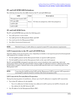
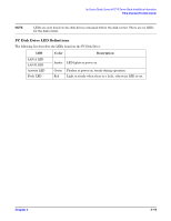
hp Carrier Grade Server bh3710 Server Blade Installation Information Fibrechannel (FC) and LAN Rear Transition Module (RTM) Blade FC and LAN RTM LED Definitions The following list describes the LEDs found on the FC and LAN RTM blade: LED Color Description Management Console LED FC Link LED LAN B LED Green Off when not plugged in; solid when plugged in. LAN A LED FC and LAN RTM Ports The FC and LAN RTM blade provides the following ports: • One LAN port for a server blade • One LAN port for the Management Blade and GSP • One serial port for the Management Blade • One Fibre Channel port bypass port. NOTE Shielded Category 5 LAN cables are required to meet FCC noise emission requirements. LAN Connectivity to the FC and LAN RTM Ports Network cabling can be structured two ways, depending on whether or not separate payload and management LAN segments are available at the site. • Put the bp2200 payload and the Management blade on separate LAN segments. • Put the bp2200 payload and the Management blade on the same LAN segment. The FC and LAN RTM is designed to provide secure access to hardware data, monitoring, and event management while leaving the payload LAN (customer LAN) for individual customer communications. This design isolates sensitive customer data on the payload LAN from the blade server monitoring data on the Management LAN. NOTE Connecting the bp2200 payload LAN and the Management LAN to separate LAN segments is encouraged to separate sensitive customer data from management data. LAN Connectivity Pre-installation Preparation During the planning phase of installation, allocate up to four IP addresses to complete LAN connectivity: • Up to three IP addresses for the bp2200. - Up to two addresses for blade hosting (one address for LAN A and one for LAN B, if desired), and - One address for the MP (formerly GSP). • One IP address for the Management Blade (SMC). Chapter 5 5-15
-
 1
1 -
2
-
3
-
4
-
5
-
6
-
7
-
8
-
9
-
10
-
11
-
12
-
13
-
14
-
15
-
16
-
17
-
18
-
19
-
20
-
21
-
22
-
23
-
24
-
25
-
26
-
27
-
28
-
29
-
 30
30 -
 31
31 -
 32
32 -
 33
33 -
 34
34 -
 35
35 -
 36
36 -
 37
37 -
 38
38 -
 39
39 -
 40
40 -
41
-
42
-
43
-
44
-
45
-
46
-
47
-
48
-
49
-
50
-
51
-
52
-
53
-
54
-
55
 |
 |