HP Management LAN Blade for bh7800 Installation Guide, Second Edition - HP Car - Page 26
Management Blade Configuration
 |
View all HP Management LAN Blade for bh7800 manuals
Add to My Manuals
Save this manual to your list of manuals |
Page 26 highlights
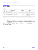
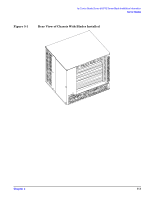
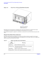
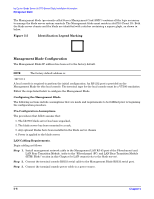
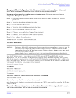
hp Carrier Grade Server bh3710 Server Blade Installation Information Management Blade The Management blade (previously called Server Management Card (SMC)) contains all the logic necessary to manage the blade server system remotely. The Management blade must reside in slot F10 (Front 10). Both the blade server chassis and the blade are identified with a sticker containing a square glyph, as shown in below. Figure 5-5 Identification Legend Marking Management Blade Configuration The Management Blade IP address has been set to the factory default. NOTE The factory default address is: 127.0.0.1 A local console is required to perform the initial configuration. An RS-232 port is provided on the Management Blade for this local console. The terminal type for the local console must be a VT100 emulation. Follow the steps listed below to configure the Management Blade. Configuring the Management Blade The following sections include assumptions that are made and requirements to be fulfilled prior to beginning the configuration procedure. Pre-Configuration Assumptions. The procedures that follow assume that: 1. The bh3710 blade server has been unpacked, 2. The blade server has been mounted in a rack, 3. Any optional blades have been installed in the blade server chassis 4. Power is applied to the blade server. LAN Cabling Requirements. Begin cabling as follows: Step 1. Install management network cable to the Management LAN RJ-45 port of the Fibrechannel and LAN Rear Transition Module. (refer to the "Fibrechannel (FC) and LAN Rear Transition Module (RTM) Blade" section in this Chapter for LAN connectivity to the blade server). Step 2. Connect the terminal console RS232 serial cable to the Management Blade RS232 serial port. Step 3. Connect the terminal console power cable to a power source. 5- 6 Chapter 5
-
 1
1 -
2
-
3
-
4
-
5
-
6
-
7
-
8
-
9
-
10
-
11
-
12
-
13
-
14
-
15
-
16
-
17
-
18
-
19
-
20
-
 21
21 -
 22
22 -
 23
23 -
 24
24 -
 25
25 -
 26
26 -
 27
27 -
 28
28 -
 29
29 -
 30
30 -
 31
31 -
32
-
33
-
34
-
35
-
36
-
37
-
38
-
39
-
40
-
41
-
42
-
43
-
44
-
45
-
46
-
47
-
48
-
49
-
50
-
51
-
52
-
53
-
54
-
55
 |
 |