HP Management LAN Blade for bh7800 Installation Guide, Second Edition - HP Car - Page 37
Step 1., Step 2., Step 3.
 |
View all HP Management LAN Blade for bh7800 manuals
Add to My Manuals
Save this manual to your list of manuals |
Page 37 highlights
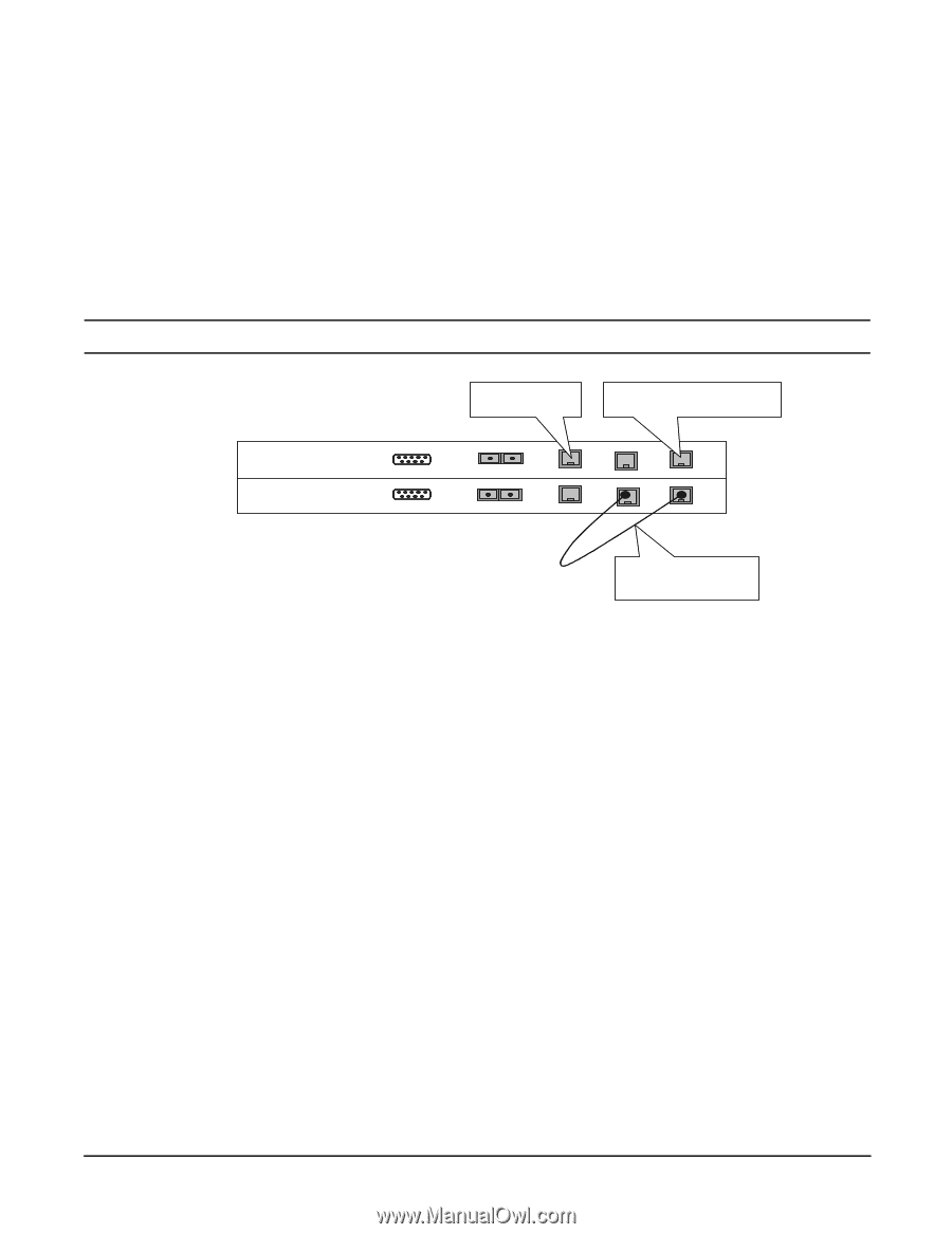
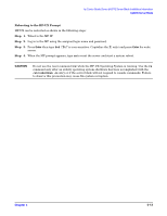
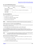
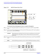
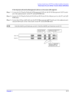
hp Carrier Grade Server bh3710 Server Blade Installation Information Fibrechannel (FC) and LAN Rear Transition Module (RTM) Blade If the Payload LAN and the Management LAN are on the same LAN segment: Step 1. In rear slot 10: Plug the Payload (A)/Management LAN into the RJ-45 Management LAN Console port (the rightmost port) on the FC and LAN RTM blade. Step 2. In rear slot 10: Plug the Payload (B) LAN into RJ-45 port B (the leftmost port) on the FC and LAN RTM blade. Step 3. In rear slot 9: Plug a LAN cable into the RJ-45 Management LAN Console port (the rightmost port) and into RJ-45 port A (the Center port) on the FC and LAN RTM blade. NOTE Only the LAN A port functions on slot 9. Only the LAN B port functions on slot 10. S lot 10 S lot 9 S eria l S e rial Co nnect to site Payload LAN-B Connect to site Payload LAN-A/M gm t LAN FC Loop B FC Loop A LAN B LAN B LAN A LAN A M gmt LAN M gmt LAN Connect cable from Payload LAN-A to Managem ent LAN Chapter 5 5-17
-
 1
1 -
2
-
3
-
4
-
5
-
6
-
7
-
8
-
9
-
10
-
11
-
12
-
13
-
14
-
15
-
16
-
17
-
18
-
19
-
20
-
21
-
22
-
23
-
24
-
25
-
26
-
27
-
28
-
29
-
30
-
31
-
 32
32 -
 33
33 -
 34
34 -
 35
35 -
 36
36 -
 37
37 -
 38
38 -
 39
39 -
 40
40 -
 41
41 -
 42
42 -
43
-
44
-
45
-
46
-
47
-
48
-
49
-
50
-
51
-
52
-
53
-
54
-
55
 |
 |