HP Management LAN Blade for bh7800 Installation Guide, Second Edition - HP Car - Page 47
Installing and Removing Carrier Blades
 |
View all HP Management LAN Blade for bh7800 manuals
Add to My Manuals
Save this manual to your list of manuals |
Page 47 highlights
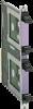
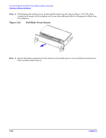
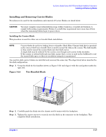
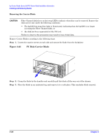
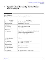
hp Carrier Grade Server bh3710 Server Blade Installation Information Installing and Removing Blades Installing and Removing Carrier Blades Procedures to be used for the installation and removal of Carrier Blades are listed below. CAUTION You must complete removal/installation steps within 3 minutes, or install slot blockers, to comply with cooling requirements. Failure to satisfy this requirement may cause loss of data when the remaining blades begin to power down. Installing the Carrier Blade This procedure is used for either one or two-slot blade installation. NOTE Carrier blades do not have locking levers or handles. Each Fibre Channel disk that is mounted in the carrier blade has a handle that is used to mount the disk in the carrier. The disk handle is then used to insert the carrier blade into the blade server. A single disk may be ordered for the carrier, even though each carrier holds two disks. If the carrier is ordered with only one disk, ensure that a cover is used on the bulkhead to seal the unused disk space so that air circulation integrity is maintained. One and two disk carrier blades are installed and removed the same way. The steps listed below describe the two-disk configuration. Step 1. Grasp the blade by the handles (shown in Figure 5-24) and align it with the card guides inside the open slot. Figure 5-24 Two-Handled Blade Step 2. Carefully push the blade into the chassis until it mates with the backplane. Step 3. Tighten the captive screws to securely seat the blade in the connector on the backplane. This completes blade installation. Chapter 5 5-27
-
 1
1 -
2
-
3
-
4
-
5
-
6
-
7
-
8
-
9
-
10
-
11
-
12
-
13
-
14
-
15
-
16
-
17
-
18
-
19
-
20
-
21
-
22
-
23
-
24
-
25
-
26
-
27
-
28
-
29
-
30
-
31
-
32
-
33
-
34
-
35
-
36
-
37
-
38
-
39
-
40
-
41
-
 42
42 -
 43
43 -
 44
44 -
 45
45 -
 46
46 -
 47
47 -
 48
48 -
 49
49 -
 50
50 -
 51
51 -
 52
52 -
53
-
54
-
55
 |
 |