HP Model 744 Installing the A4315A and A4316A HCRX/VME Graphics Options - Page 27
Install front panel extension plate, if needed., Installing the HCRX/VME Graphics Hardware
 |
View all HP Model 744 manuals
Add to My Manuals
Save this manual to your list of manuals |
Page 27 highlights
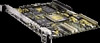
Installing the HCRX/VME Graphics Hardware 4. Install front panel extension plate, if needed. If the SBC did not have any option boards or an expansion kit installed, you need to install the front panel extension plate that came with the HCRX/VME kit, as follows: a. Remove the EMI gaskets from the top lip of the SBC's front panel. b. Place the front panel extension plate on the SBC's front panel with its tabs behind the existing front panel, as shown in Figure 2-5. Front Panel Extension Plate Figure 2-5. Installing the Front Panel Extension Plate c. Insert the four M2x.45x5mm screws through the existing front panel and into the front panel extension and tighten them with a #1 Pozidriv screwdriver. See Figure 2-5. 2-7
-
 1
1 -
2
-
3
-
4
-
5
-
6
-
7
-
8
-
9
-
10
-
11
-
12
-
13
-
14
-
15
-
16
-
17
-
18
-
19
-
20
-
21
-
 22
22 -
 23
23 -
 24
24 -
 25
25 -
 26
26 -
 27
27 -
 28
28 -
 29
29 -
 30
30 -
 31
31 -
 32
32 -
33
-
34
-
35
-
36
-
37
-
38
-
39
-
40
-
41
-
42
-
43
-
44
-
45
-
46
-
47
-
48
-
49
-
50
-
51
-
52
 |
 |

Installing the HCRX/VME Graphics Hardware
2–7
4.
Install front panel extension plate, if needed.
If the SBC did not have any option boards or an expansion kit installed, you need to
install the front panel extension plate that came with the HCRX/VME kit, as follows:
a.
Remove the EMI gaskets from the top lip of the SBC’s front panel.
b.
Place the front panel extension plate on the SBC’s front panel with its tabs behind
the existing front panel, as shown in Figure 2–5.
Front Panel Extension Plate
Figure 2–5.
Installing the Front Panel Extension Plate
c.
Insert the four M2x.45x5mm screws through the existing front panel and into the
front panel extension and tighten them with a #1 Pozidriv screwdriver.
See Figure 2–5.