HP Model 744 Installing the A4315A and A4316A HCRX/VME Graphics Options - Page 29
See
 |
View all HP Model 744 manuals
Add to My Manuals
Save this manual to your list of manuals |
Page 29 highlights
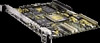
Installing the HCRX/VME Graphics Hardware b. Align the connector on the bottom of the HCRX/VME graphics board with the GSC connector on the SBC. See Figure 2-6. c. Gently press down on the graphics board until the connectors are fully seated. d. Insert the four M2x.45x12mm screws through the bottom of the SBC and through the VMEbus connectors into the standoffs on the HCRX/VME graphics board. See Figure 2-6. e. Use a #1 Pozidriv screwdriver to tighten the four screws. f. Insert the the two M2x.45x6mm screws through the bottom of the SBC into the remaining two standoffs on the HCRX/VME graphics board. See Figure 2-6. g. Use a #1 Pozidriv screwdriver to tighten the two screws. h. Install two M2x.45x5mm screws through the front panel extension plate on either side of the HCRX/VME board's video connector to secure the video connector plate. See Figure 2-6. i. Use a #1 Pozidriv screwdriver to tighten the two screws. 2-9
-
 1
1 -
2
-
3
-
4
-
5
-
6
-
7
-
8
-
9
-
10
-
11
-
12
-
13
-
14
-
15
-
16
-
17
-
18
-
19
-
20
-
21
-
22
-
23
-
 24
24 -
 25
25 -
 26
26 -
 27
27 -
 28
28 -
 29
29 -
 30
30 -
 31
31 -
 32
32 -
 33
33 -
 34
34 -
35
-
36
-
37
-
38
-
39
-
40
-
41
-
42
-
43
-
44
-
45
-
46
-
47
-
48
-
49
-
50
-
51
-
52
 |
 |
