HP Pavilion HDX9309TX HP Pavilion HDX Entertainmet Series Notebook PC - Mainte - Page 44
Display assembly internal components, Remove the display bezel
 |
View all HP Pavilion HDX9309TX manuals
Add to My Manuals
Save this manual to your list of manuals |
Page 44 highlights
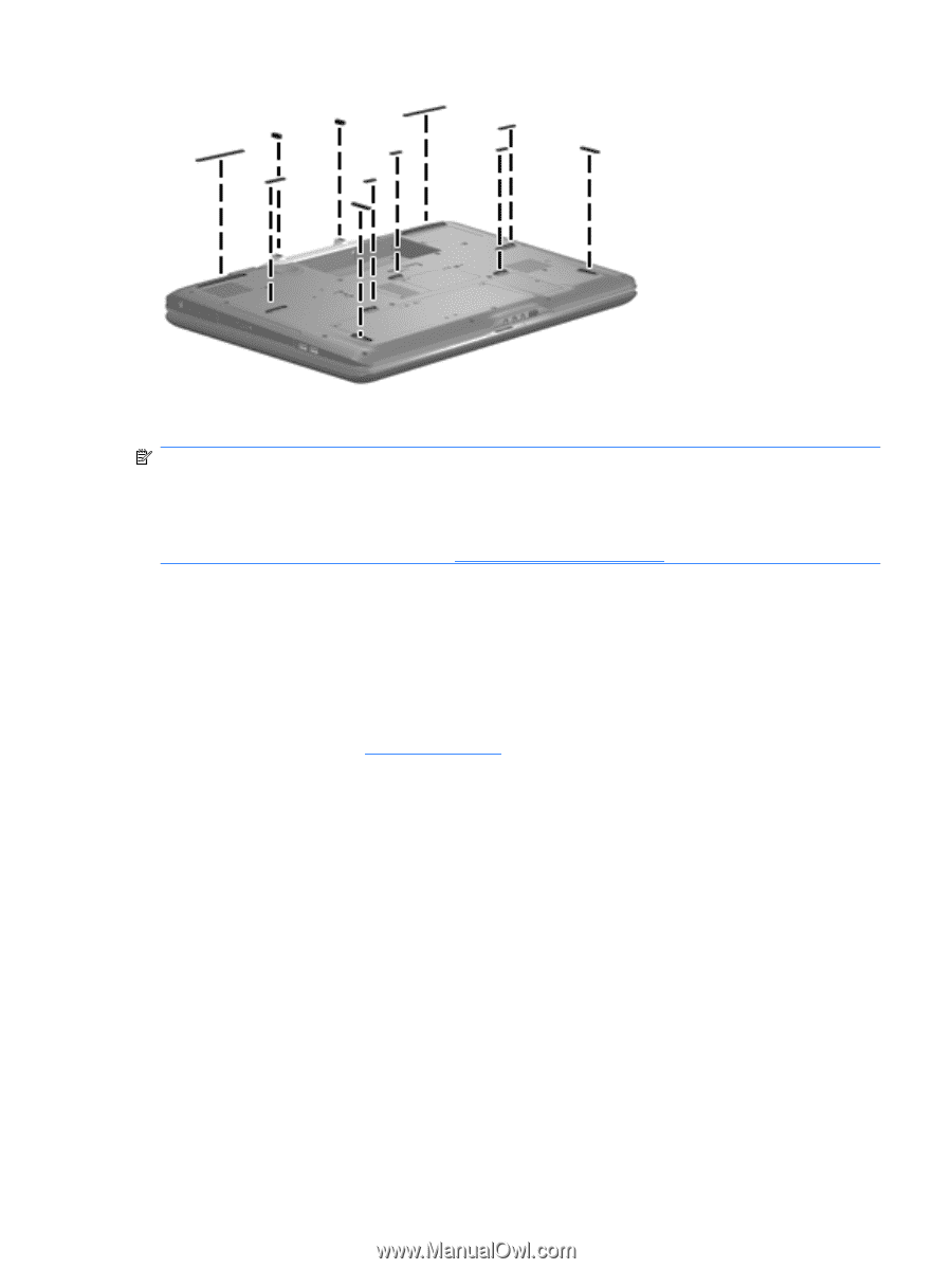
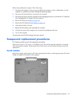
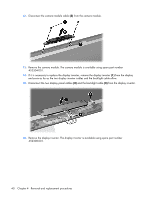
Display assembly internal components NOTE: If it has been determined that the display bezel, camera module, display inverter, display panel, or speakers are the components that must be replaced to complete the computer repair, the display assembly does not have to be completely removed from the computer. Replacement of these components can be completed by removing only the display bezel. Follow the procedures in this section to replace the display bezel, camera module, display inverter, display panel, or speakers. For information on replacing the entire display assembly, see Display assembly on page 60. Before removing the display bezel, follow these steps: 1. Shut down the computer. If you are unsure whether the computer is off or in Hibernation, turn the computer on, and then shut it down through the operating system. 2. Disconnect all external devices connected to the computer. 3. Disconnect the power from the computer by first unplugging the power cord from the AC outlet and then unplugging the AC adapter from the computer. 4. Remove the battery (see Battery on page 36). Remove the display bezel: 1. Turn the computer display-side up, with the rear panel toward you. 2. Open the computer as far as possible. 3. Remove the two rubber screw covers from the back of the display assembly (1). All rubber screw covers and logo labels removed in this section are included in the Display Rubber Pad Kit, spare part number 454595-001. Component replacement procedures 37
-
 1
1 -
2
-
3
-
4
-
5
-
6
-
7
-
8
-
9
-
10
-
11
-
12
-
13
-
14
-
15
-
16
-
17
-
18
-
19
-
20
-
21
-
22
-
23
-
24
-
25
-
26
-
27
-
28
-
29
-
30
-
31
-
32
-
33
-
34
-
35
-
36
-
37
-
38
-
 39
39 -
 40
40 -
 41
41 -
 42
42 -
 43
43 -
 44
44 -
 45
45 -
 46
46 -
 47
47 -
 48
48 -
 49
49 -
50
-
51
-
52
-
53
-
54
-
55
-
56
-
57
-
58
-
59
-
60
-
61
-
62
-
63
-
64
-
65
-
66
-
67
-
68
-
69
-
70
-
71
-
72
-
73
-
74
-
75
-
76
-
77
-
78
-
79
-
80
-
81
-
82
-
83
-
84
-
85
-
86
-
87
-
88
-
89
-
90
-
91
-
92
-
93
-
94
-
95
-
96
-
97
-
98
-
99
-
100
-
101
-
102
-
103
-
104
-
105
-
106
-
107
-
108
-
109
-
110
-
111
-
112
-
113
-
114
-
115
-
116
-
117
-
118
-
119
-
120
-
121
-
122
-
123
-
124
-
125
-
126
-
127
-
128
-
129
-
130
-
131
-
132
-
133
-
134
-
135
-
136
-
137
-
138
-
139
-
140
-
141
 |
 |