HP Pavilion HDX9309TX HP Pavilion HDX Entertainmet Series Notebook PC - Mainte - Page 81
RTC battery, that secure the audio connector board to the base
 |
View all HP Pavilion HDX9309TX manuals
Add to My Manuals
Save this manual to your list of manuals |
Page 81 highlights
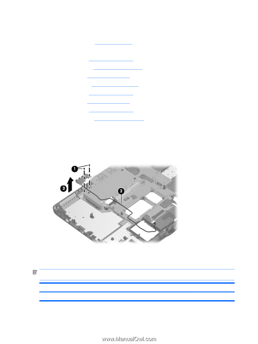
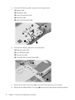
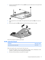
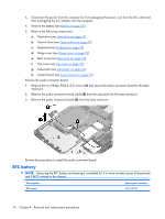
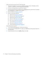
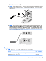
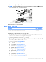
3. Disconnect the power from the computer by first unplugging the power cord from the AC outlet and then unplugging the AC adapter from the computer. 4. Remove the battery (see Battery on page 36). 5. Remove the following components: a. Hard drive (see Hard drive on page 42) b. Optical drive (see Optical drive on page 49) c. Keyboard (see Keyboard on page 50) d. Hinge cover (see Hinge cover on page 52) e. Rear cover (see Rear cover on page 53) f. Top cover (see Top cover on page 55) g. Subwoofer (see Subwoofer on page 67) h. System board (see System board on page 70) Remove the audio connector board: 1. Remove the two Phillips PM2.5×5.0 screws (1) that secure the audio connector board to the base enclosure. 2. Remove the audio connector board cable (2) from the clips built into the base enclosure. 3. Remove the audio connector board (3) from the base enclosure. Reverse this procedure to install the audio connector board. RTC battery NOTE: Removing the RTC battery and leaving it uninstalled for 5 or more minutes causes all passwords and CMOS settings to be cleared. Description RTC battery Spare part number 452319-001 74 Chapter 4 Removal and replacement procedures
-
 1
1 -
2
-
3
-
4
-
5
-
6
-
7
-
8
-
9
-
10
-
11
-
12
-
13
-
14
-
15
-
16
-
17
-
18
-
19
-
20
-
21
-
22
-
23
-
24
-
25
-
26
-
27
-
28
-
29
-
30
-
31
-
32
-
33
-
34
-
35
-
36
-
37
-
38
-
39
-
40
-
41
-
42
-
43
-
44
-
45
-
46
-
47
-
48
-
49
-
50
-
51
-
52
-
53
-
54
-
55
-
56
-
57
-
58
-
59
-
60
-
61
-
62
-
63
-
64
-
65
-
66
-
67
-
68
-
69
-
70
-
71
-
72
-
73
-
74
-
75
-
 76
76 -
 77
77 -
 78
78 -
 79
79 -
 80
80 -
 81
81 -
 82
82 -
 83
83 -
 84
84 -
 85
85 -
 86
86 -
87
-
88
-
89
-
90
-
91
-
92
-
93
-
94
-
95
-
96
-
97
-
98
-
99
-
100
-
101
-
102
-
103
-
104
-
105
-
106
-
107
-
108
-
109
-
110
-
111
-
112
-
113
-
114
-
115
-
116
-
117
-
118
-
119
-
120
-
121
-
122
-
123
-
124
-
125
-
126
-
127
-
128
-
129
-
130
-
131
-
132
-
133
-
134
-
135
-
136
-
137
-
138
-
139
-
140
-
141
 |
 |