HP Pavilion HDX9309TX HP Pavilion HDX Entertainmet Series Notebook PC - Mainte - Page 61
Remove the Phillips PM2.5×4.0 screw, Remove the four Phillips PM2.5×4.0 broad-head screws
 |
View all HP Pavilion HDX9309TX manuals
Add to My Manuals
Save this manual to your list of manuals |
Page 61 highlights
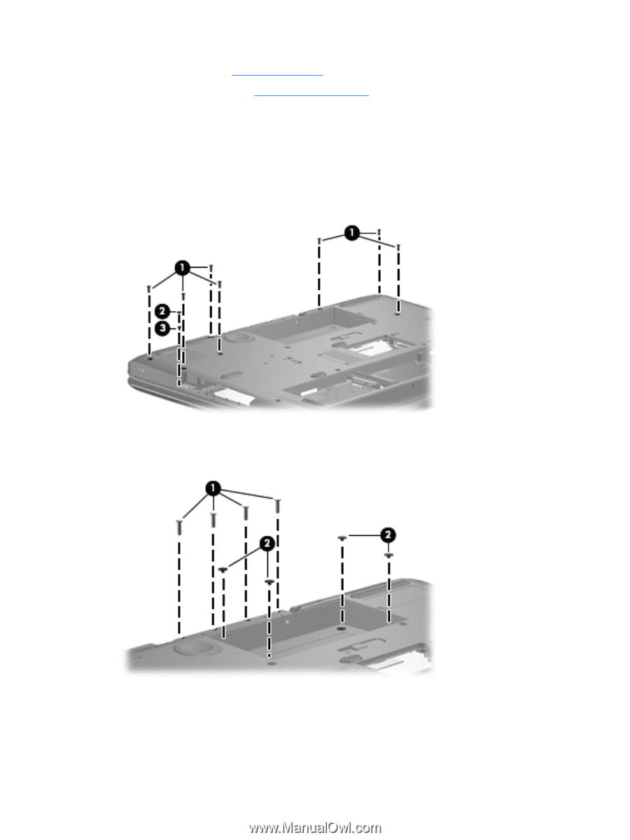
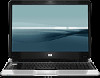
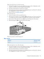
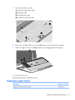
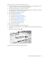
4. Remove the battery (see Battery on page 36). 5. Remove the hinge cover (see Hinge cover on page 52). Remove the rear cover: 1. Position the computer with the front toward you. 2. Remove the seven Phillips PM2.5×8.0 screws (1) that secure the rear cover to the computer. 3. Remove the Mylar screw cover (2) in the optical drive bay. This screw cover is available in the Rubber Feet Kit, spare part number 452320-001. 4. Remove the Phillips PM2.5×4.0 screw (3) that secures the rear cover to the computer. 5. Remove the four Phillips PM3.0×12.0 screws (1) that secure the rear cover to the computer. 6. Remove the four Phillips PM2.5×4.0 broad-head screws (2) that secure the rear cover to the computer. 7. Turn the computer right-side up, with the front toward you. 8. Open the computer as far as possible. 54 Chapter 4 Removal and replacement procedures
-
 1
1 -
2
-
3
-
4
-
5
-
6
-
7
-
8
-
9
-
10
-
11
-
12
-
13
-
14
-
15
-
16
-
17
-
18
-
19
-
20
-
21
-
22
-
23
-
24
-
25
-
26
-
27
-
28
-
29
-
30
-
31
-
32
-
33
-
34
-
35
-
36
-
37
-
38
-
39
-
40
-
41
-
42
-
43
-
44
-
45
-
46
-
47
-
48
-
49
-
50
-
51
-
52
-
53
-
54
-
55
-
 56
56 -
 57
57 -
 58
58 -
 59
59 -
 60
60 -
 61
61 -
 62
62 -
 63
63 -
 64
64 -
 65
65 -
 66
66 -
67
-
68
-
69
-
70
-
71
-
72
-
73
-
74
-
75
-
76
-
77
-
78
-
79
-
80
-
81
-
82
-
83
-
84
-
85
-
86
-
87
-
88
-
89
-
90
-
91
-
92
-
93
-
94
-
95
-
96
-
97
-
98
-
99
-
100
-
101
-
102
-
103
-
104
-
105
-
106
-
107
-
108
-
109
-
110
-
111
-
112
-
113
-
114
-
115
-
116
-
117
-
118
-
119
-
120
-
121
-
122
-
123
-
124
-
125
-
126
-
127
-
128
-
129
-
130
-
131
-
132
-
133
-
134
-
135
-
136
-
137
-
138
-
139
-
140
-
141
 |
 |