HP Pavilion HDX9309TX HP Pavilion HDX Entertainmet Series Notebook PC - Mainte - Page 46
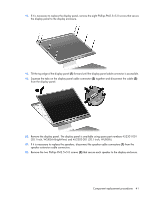
secure the camera module to the display enclosure.
 |
View all HP Pavilion HDX9309TX manuals
Add to My Manuals
Save this manual to your list of manuals |
Page 46 highlights
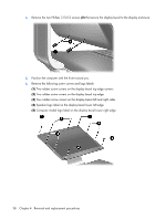
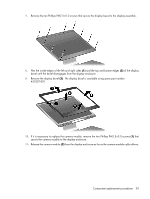
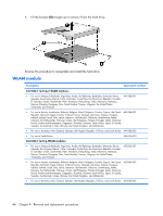
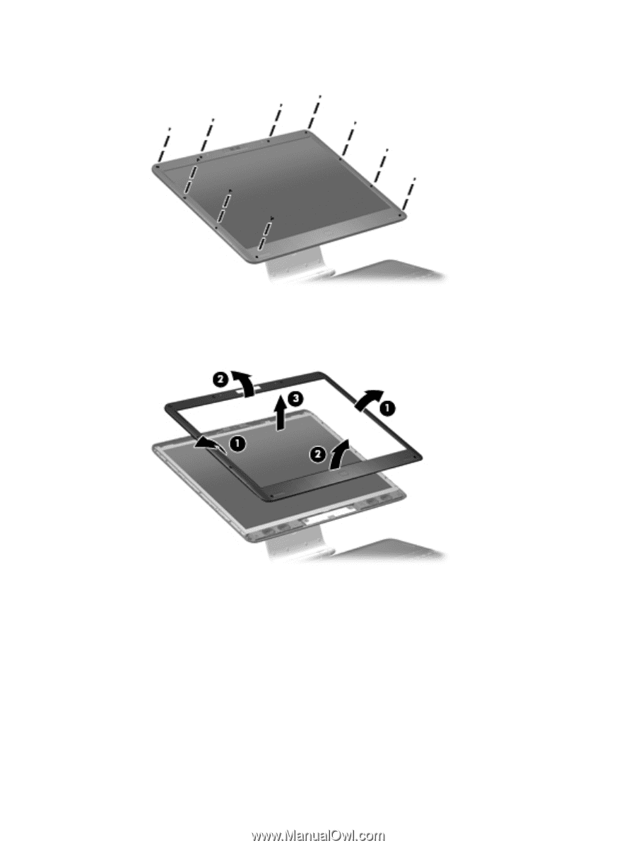
7. Remove the ten Phillips PM2.5×5.0 screws that secure the display bezel to the display assembly. 8. Flex the inside edges of the left and right sides (1) and the top and bottom edges (2) of the display bezel until the bezel disengages from the display enclosure. 9. Remove the display bezel (3). The display bezel is available using spare part number 452307-001. 10. If it is necessary to replace the camera module, remove the two Phillips PM2.5×5.0 screws (1) that secure the camera module to the display enclosure. 11. Release the camera module (2) from the display enclosure as far as the camera module cable allows. Component replacement procedures 39
-
 1
1 -
2
-
3
-
4
-
5
-
6
-
7
-
8
-
9
-
10
-
11
-
12
-
13
-
14
-
15
-
16
-
17
-
18
-
19
-
20
-
21
-
22
-
23
-
24
-
25
-
26
-
27
-
28
-
29
-
30
-
31
-
32
-
33
-
34
-
35
-
36
-
37
-
38
-
39
-
40
-
 41
41 -
 42
42 -
 43
43 -
 44
44 -
 45
45 -
 46
46 -
 47
47 -
 48
48 -
 49
49 -
 50
50 -
 51
51 -
52
-
53
-
54
-
55
-
56
-
57
-
58
-
59
-
60
-
61
-
62
-
63
-
64
-
65
-
66
-
67
-
68
-
69
-
70
-
71
-
72
-
73
-
74
-
75
-
76
-
77
-
78
-
79
-
80
-
81
-
82
-
83
-
84
-
85
-
86
-
87
-
88
-
89
-
90
-
91
-
92
-
93
-
94
-
95
-
96
-
97
-
98
-
99
-
100
-
101
-
102
-
103
-
104
-
105
-
106
-
107
-
108
-
109
-
110
-
111
-
112
-
113
-
114
-
115
-
116
-
117
-
118
-
119
-
120
-
121
-
122
-
123
-
124
-
125
-
126
-
127
-
128
-
129
-
130
-
131
-
132
-
133
-
134
-
135
-
136
-
137
-
138
-
139
-
140
-
141
 |
 |
7
.
Remove the ten Phillips PM2.5×5.0 screws that secure the display bezel to the display assembly.
8
.
Flex the inside edges of the left and right sides
(1)
and the top and bottom edges
(2)
of the display
bezel until the bezel disengages from the display enclosure.
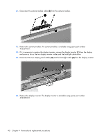
9
.
Remove the display bezel
(3)
. The display bezel is available using spare part number
452307-001.
10
.
If it is necessary to replace the camera module, remove the two Phillips PM2.5×5.0 screws
(1)
that
secure the camera module to the display enclosure.
11
.
Release the camera module
(2)
from the display enclosure as far as the camera module cable allows.
Component replacement procedures
39