HP Pavilion HDX9309TX HP Pavilion HDX Entertainmet Series Notebook PC - Mainte - Page 54
Memory module, The TV tuner module is designed with a notch
 |
View all HP Pavilion HDX9309TX manuals
Add to My Manuals
Save this manual to your list of manuals |
Page 54 highlights
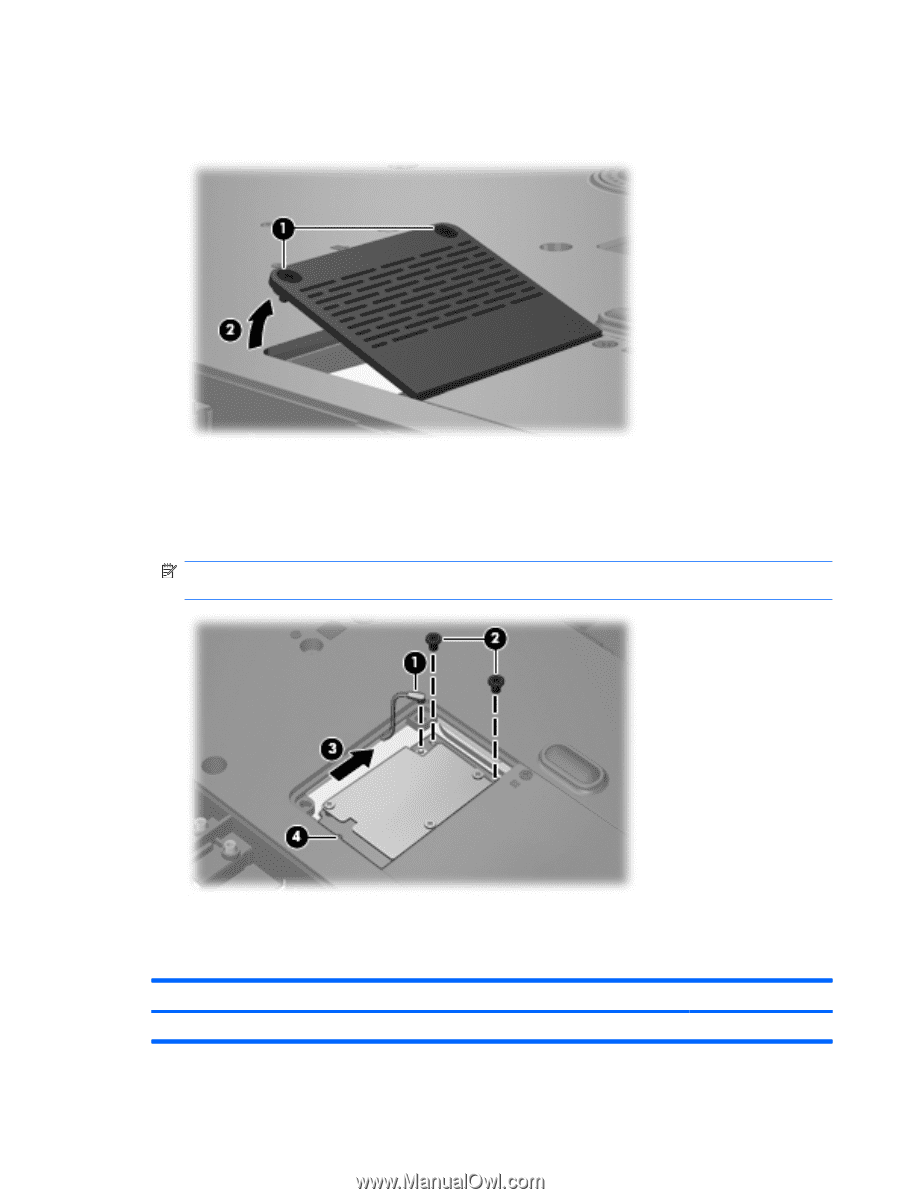
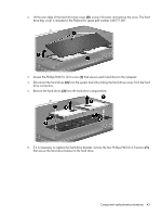
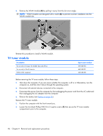
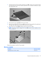
3. Lift the left side of the TV tuner module compartment cover (2), swing the cover up and to the right, and remove the cover. The TV tuner module compartment cover is included in the Plastics Kit, spare part number 448171-001. 4. Disconnect the TV tuner cable (1) from the TV tuner module. 5. Remove the two Phillips PM2.5×5.0 screws (2) that secure the TV tuner module to the system board. (The edge of the module opposite the slot rises away from the computer.) 6. Remove the TV tuner module (3) by pulling it away from the slot at an angle. NOTE: The TV tuner module is designed with a notch (4) to prevent incorrect installation into the TV tuner module slot. Reverse this procedure to install the TV tuner module. Memory module Description 2048-MB (667-MHz, PC2-5300, 1-DIMM) Spare part number 448151-001 Component replacement procedures 47
-
 1
1 -
2
-
3
-
4
-
5
-
6
-
7
-
8
-
9
-
10
-
11
-
12
-
13
-
14
-
15
-
16
-
17
-
18
-
19
-
20
-
21
-
22
-
23
-
24
-
25
-
26
-
27
-
28
-
29
-
30
-
31
-
32
-
33
-
34
-
35
-
36
-
37
-
38
-
39
-
40
-
41
-
42
-
43
-
44
-
45
-
46
-
47
-
48
-
 49
49 -
 50
50 -
 51
51 -
 52
52 -
 53
53 -
 54
54 -
 55
55 -
 56
56 -
 57
57 -
 58
58 -
 59
59 -
60
-
61
-
62
-
63
-
64
-
65
-
66
-
67
-
68
-
69
-
70
-
71
-
72
-
73
-
74
-
75
-
76
-
77
-
78
-
79
-
80
-
81
-
82
-
83
-
84
-
85
-
86
-
87
-
88
-
89
-
90
-
91
-
92
-
93
-
94
-
95
-
96
-
97
-
98
-
99
-
100
-
101
-
102
-
103
-
104
-
105
-
106
-
107
-
108
-
109
-
110
-
111
-
112
-
113
-
114
-
115
-
116
-
117
-
118
-
119
-
120
-
121
-
122
-
123
-
124
-
125
-
126
-
127
-
128
-
129
-
130
-
131
-
132
-
133
-
134
-
135
-
136
-
137
-
138
-
139
-
140
-
141
 |
 |