HP Pavilion HDX9309TX HP Pavilion HDX Entertainmet Series Notebook PC - Mainte - Page 77
System board, Battery, on Hard drive, Optical drive, Keyboard, Hinge cover, Rear cover
 |
View all HP Pavilion HDX9309TX manuals
Add to My Manuals
Save this manual to your list of manuals |
Page 77 highlights
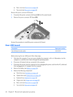
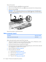
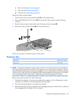
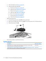
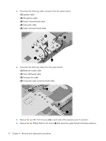
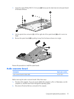
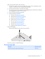
4. Remove the battery (see Battery on page 36). 5. Remove the following components: a. Hard drive (see Hard drive on page 42) b. Optical drive (see Optical drive on page 49) c. Keyboard (see Keyboard on page 50) d. Hinge cover (see Hinge cover on page 52) e. Rear cover (see Rear cover on page 53) f. Top cover (see Top cover on page 55) g. Subwoofer (see Subwoofer on page 67) Remove the processor fan: 1. Disconnect the processor fan cable (1) from the system board. 2. Remove the two Phillips PM2.5×8.0 screws (2) that secure the processor fan to the base enclosure. 3. Remove the processor fan (3). Reverse this procedure to install the processor fan. System board Description Spare part number System board for use in computer models with ATI graphics (includes power connector cable, ExpressCard assembly, and replacement thermal material) 448145-001 System board for use in computer models with either ATI or nVidia graphics (includes power connector 464591-001 cable, ExpressCard assembly, and replacement thermal material) 70 Chapter 4 Removal and replacement procedures
-
 1
1 -
2
-
3
-
4
-
5
-
6
-
7
-
8
-
9
-
10
-
11
-
12
-
13
-
14
-
15
-
16
-
17
-
18
-
19
-
20
-
21
-
22
-
23
-
24
-
25
-
26
-
27
-
28
-
29
-
30
-
31
-
32
-
33
-
34
-
35
-
36
-
37
-
38
-
39
-
40
-
41
-
42
-
43
-
44
-
45
-
46
-
47
-
48
-
49
-
50
-
51
-
52
-
53
-
54
-
55
-
56
-
57
-
58
-
59
-
60
-
61
-
62
-
63
-
64
-
65
-
66
-
67
-
68
-
69
-
70
-
71
-
 72
72 -
 73
73 -
 74
74 -
 75
75 -
 76
76 -
 77
77 -
 78
78 -
 79
79 -
 80
80 -
 81
81 -
 82
82 -
83
-
84
-
85
-
86
-
87
-
88
-
89
-
90
-
91
-
92
-
93
-
94
-
95
-
96
-
97
-
98
-
99
-
100
-
101
-
102
-
103
-
104
-
105
-
106
-
107
-
108
-
109
-
110
-
111
-
112
-
113
-
114
-
115
-
116
-
117
-
118
-
119
-
120
-
121
-
122
-
123
-
124
-
125
-
126
-
127
-
128
-
129
-
130
-
131
-
132
-
133
-
134
-
135
-
136
-
137
-
138
-
139
-
140
-
141
 |
 |