HP Pavilion HDX9309TX HP Pavilion HDX Entertainmet Series Notebook PC - Mainte - Page 87
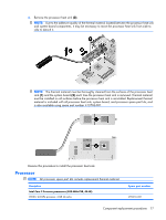
The thermal material must be thoroughly cleaned from the surfaces of the video board
 |
View all HP Pavilion HDX9309TX manuals
Add to My Manuals
Save this manual to your list of manuals |
Page 87 highlights
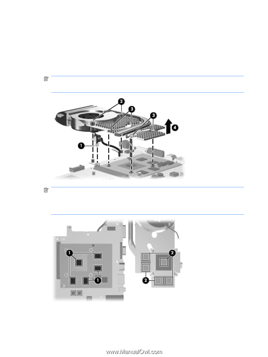
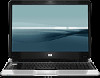
Remove the video board heat sink: 1. Turn the system board upside down, with the front toward you. 2. Disconnect the video board fan cable (1) from the system board. 3. Loosen the two Phillips PM2.5×9.0 captive screws (2) and the four silver Phillips PM2.0×5.0 captive screws (3) that secure the video board heat sink to the system board. 4. Remove the video board heat sink (4). NOTE: Due to the adhesive quality of the thermal material located between the video board heat sink and system board components, it may be necessary to move the video board heat sink from side to side to detach it. NOTE: The thermal material must be thoroughly cleaned from the surfaces of the video board components (1) and the video board heat sink (2) each time the video board heat sink is removed. Thermal material must be installed on all surfaces before the video board heat sink is reinstalled. Replacement thermal material is included with all video board heat sink and video board spare part kits, and is also available using spare part number 413706-001. Reverse this procedure to install the video board heat sink. 80 Chapter 4 Removal and replacement procedures
-
 1
1 -
2
-
3
-
4
-
5
-
6
-
7
-
8
-
9
-
10
-
11
-
12
-
13
-
14
-
15
-
16
-
17
-
18
-
19
-
20
-
21
-
22
-
23
-
24
-
25
-
26
-
27
-
28
-
29
-
30
-
31
-
32
-
33
-
34
-
35
-
36
-
37
-
38
-
39
-
40
-
41
-
42
-
43
-
44
-
45
-
46
-
47
-
48
-
49
-
50
-
51
-
52
-
53
-
54
-
55
-
56
-
57
-
58
-
59
-
60
-
61
-
62
-
63
-
64
-
65
-
66
-
67
-
68
-
69
-
70
-
71
-
72
-
73
-
74
-
75
-
76
-
77
-
78
-
79
-
80
-
81
-
 82
82 -
 83
83 -
 84
84 -
 85
85 -
 86
86 -
 87
87 -
 88
88 -
 89
89 -
 90
90 -
 91
91 -
 92
92 -
93
-
94
-
95
-
96
-
97
-
98
-
99
-
100
-
101
-
102
-
103
-
104
-
105
-
106
-
107
-
108
-
109
-
110
-
111
-
112
-
113
-
114
-
115
-
116
-
117
-
118
-
119
-
120
-
121
-
122
-
123
-
124
-
125
-
126
-
127
-
128
-
129
-
130
-
131
-
132
-
133
-
134
-
135
-
136
-
137
-
138
-
139
-
140
-
141
 |
 |