HP Pavilion Media Center m7600 HP Media Center PC - Getting Started Guide - Page 18
HP Media Center PC Getting Started Guide, Connector, Icon/label, Description and function Continued
 |
View all HP Pavilion Media Center m7600 manuals
Add to My Manuals
Save this manual to your list of manuals |
Page 18 highlights
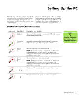
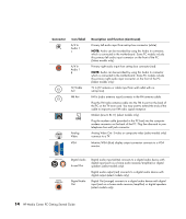
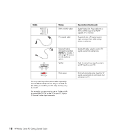
Connector Icon/label A/V In Audio 1 L A/V In Audio 1 R TV/Cable Ant FM Ant LINE Analog Video VGA Description and function (Continued) Primary left audio input from set-top box connector (white). NOTE: Audio can be recorded by using this Audio In connector, which is connected to the motherboard. Some PC models include this primary left audio input connector on the front of the PC. (Select models only.) Primary right audio input from set-top box connector (red). NOTE: Audio can be recorded by using this Audio In connector which is connected to the motherboard. Some PC models include this primary right audio input connector on the front of the PC. (Select models only.) TV In (TV antenna or cable input from wall outlet with no set-top box). FM In (radio antenna input) connects to the FM antenna cable. Plug the FM radio antenna cable into the FM In port on the back of the PC on the TV tuner card. You may want to extend the ends of the cable to improve your FM radio signal reception. Modem (Line In RJ-11) (select models only). Plug the modem cable (provided in the PC box) into the computer modem connector on the back of the PC. Plug the other end to your telephone line wall jack connector. Analog Video Out: S-video or composite video (select models only) connects to a TV. Monitor/VGA (blue) display output connector connects to a VGA monitor. DIGITAL AUDIO OUT Digital Audio In and Out Digital Audio Out Digital audio input (white) connects to a digital audio device with digital input (such as a home audio receiver/amplifier) or digital speakers (select models only). Digital audio output (red) connects to a digital audio device with digital output (select models only). Digital Out (orange) connects to a digital audio device with digital input (such as a home audio receiver/amplifier) or digital speakers (select models only). 14 HP Media Center PC Getting Started Guide
-
 1
1 -
2
-
3
-
4
-
5
-
6
-
7
-
8
-
9
-
10
-
11
-
12
-
 13
13 -
 14
14 -
 15
15 -
 16
16 -
 17
17 -
 18
18 -
 19
19 -
 20
20 -
 21
21 -
 22
22 -
 23
23 -
24
-
25
-
26
-
27
-
28
-
29
-
30
-
31
-
32
-
33
-
34
-
35
-
36
-
37
-
38
-
39
-
40
-
41
-
42
-
43
-
44
-
45
-
46
-
47
-
48
-
49
-
50
-
51
-
52
-
53
-
54
-
55
-
56
-
57
-
58
-
59
-
60
-
61
-
62
-
63
-
64
-
65
-
66
-
67
-
68
-
69
-
70
-
71
-
72
-
73
-
74
-
75
-
76
-
77
-
78
-
79
-
80
-
81
-
82
-
83
-
84
-
85
-
86
 |
 |
