HP Pavilion dv7-5000 HP Pavilion dv7 Entertainment PC - Maintenance and Servic - Page 105
Remove the fan/heat sink assembly
 |
View all HP Pavilion dv7-5000 manuals
Add to My Manuals
Save this manual to your list of manuals |
Page 105 highlights
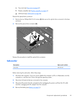
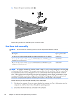
3. Disconnect the power from the computer by first unplugging the power cord from the AC outlet and then unplugging the AC adapter from the computer. 4. Remove the battery (see Battery on page 51). 5. Remove the primary hard drive cover (see Primary hard drive cover on page 52). 6. Remove the following components: a. Hard drive (see Hard drive on page 53). b. Secondary hard drive (see Secondary hard drive on page 55). c. Optical drive (see Optical drive on page 63). d. Keyboard (see Keyboard on page 65). e. Top cover (see Top cover on page 67). f. Display assembly (see Display assembly on page 73). g. System board (see System board on page 83). h. USB board (see USB board on page 86). Remove the fan/heat sink assembly: NOTE: Steps 1 through 4 apply only to models with discrete subsystem memory on the system board. See steps 5 through 8 apply only to models with UMA subsystem memory on the system board. 1. Turn the system board upside down, with the expansion port and external monitor port toward you. 2. Loosen the seven PM2.5×3.0 Phillips captive screws (1) that secure the fan/heat sink assembly to the system board. Component replacement procedures 95
-
 1
1 -
2
-
3
-
4
-
5
-
6
-
7
-
8
-
9
-
10
-
11
-
12
-
13
-
14
-
15
-
16
-
17
-
18
-
19
-
20
-
21
-
22
-
23
-
24
-
25
-
26
-
27
-
28
-
29
-
30
-
31
-
32
-
33
-
34
-
35
-
36
-
37
-
38
-
39
-
40
-
41
-
42
-
43
-
44
-
45
-
46
-
47
-
48
-
49
-
50
-
51
-
52
-
53
-
54
-
55
-
56
-
57
-
58
-
59
-
60
-
61
-
62
-
63
-
64
-
65
-
66
-
67
-
68
-
69
-
70
-
71
-
72
-
73
-
74
-
75
-
76
-
77
-
78
-
79
-
80
-
81
-
82
-
83
-
84
-
85
-
86
-
87
-
88
-
89
-
90
-
91
-
92
-
93
-
94
-
95
-
96
-
97
-
98
-
99
-
 100
100 -
 101
101 -
 102
102 -
 103
103 -
 104
104 -
 105
105 -
 106
106 -
 107
107 -
 108
108 -
 109
109 -
 110
110 -
111
-
112
-
113
-
114
-
115
-
116
-
117
-
118
-
119
-
120
-
121
-
122
-
123
-
124
-
125
-
126
-
127
-
128
-
129
-
130
-
131
-
132
-
133
-
134
-
135
-
136
-
137
-
138
-
139
-
140
-
141
-
142
-
143
-
144
-
145
-
146
-
147
-
148
-
149
-
150
 |
 |