HP Pavilion dv7-5000 HP Pavilion dv7 Entertainment PC - Maintenance and Servic - Page 89
Two Phillips PM2.5×5.0 screws, and the bottom edge of
 |
View all HP Pavilion dv7-5000 manuals
Add to My Manuals
Save this manual to your list of manuals |
Page 89 highlights
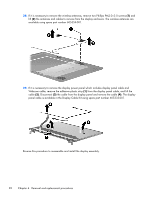
18. If it is necessary to replace the display bezel or any of the display assembly internal components, remove the following screw covers and screws: (1) Two rubber screw covers on the display bezel bottom edge. The display rubber screw covers are included in the Display Rubber Kit, spare part number 605341-001. (2) Two Phillips PM2.5×5.0 screws 19. Slide off each hinge cover to remove from the display assembly. 20. Flex the inside edges of the top edge (1), the left and right sides (2), and the bottom edge of the display bezel (3) until the bezel disengages from the display enclosure. Component replacement procedures 79
-
 1
1 -
2
-
3
-
4
-
5
-
6
-
7
-
8
-
9
-
10
-
11
-
12
-
13
-
14
-
15
-
16
-
17
-
18
-
19
-
20
-
21
-
22
-
23
-
24
-
25
-
26
-
27
-
28
-
29
-
30
-
31
-
32
-
33
-
34
-
35
-
36
-
37
-
38
-
39
-
40
-
41
-
42
-
43
-
44
-
45
-
46
-
47
-
48
-
49
-
50
-
51
-
52
-
53
-
54
-
55
-
56
-
57
-
58
-
59
-
60
-
61
-
62
-
63
-
64
-
65
-
66
-
67
-
68
-
69
-
70
-
71
-
72
-
73
-
74
-
75
-
76
-
77
-
78
-
79
-
80
-
81
-
82
-
83
-
 84
84 -
 85
85 -
 86
86 -
 87
87 -
 88
88 -
 89
89 -
 90
90 -
 91
91 -
 92
92 -
 93
93 -
 94
94 -
95
-
96
-
97
-
98
-
99
-
100
-
101
-
102
-
103
-
104
-
105
-
106
-
107
-
108
-
109
-
110
-
111
-
112
-
113
-
114
-
115
-
116
-
117
-
118
-
119
-
120
-
121
-
122
-
123
-
124
-
125
-
126
-
127
-
128
-
129
-
130
-
131
-
132
-
133
-
134
-
135
-
136
-
137
-
138
-
139
-
140
-
141
-
142
-
143
-
144
-
145
-
146
-
147
-
148
-
149
-
150
 |
 |
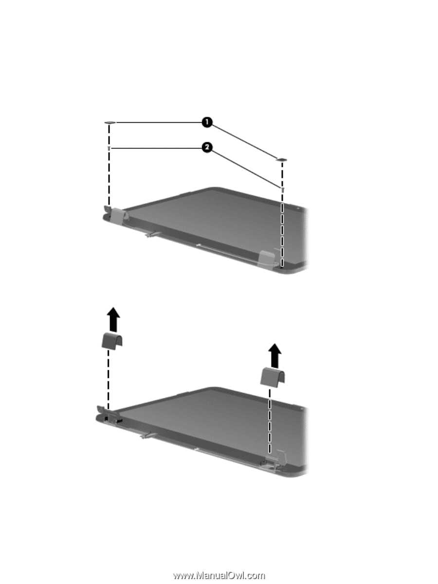
18.
If it is necessary to replace the display bezel or any of the display assembly internal components,
remove the following screw covers and screws:
(1)
Two rubber screw covers on the display bezel bottom edge. The display rubber screw covers
are included in the Display Rubber Kit, spare part number 605341-001.
(2)
Two Phillips PM2.5×5.0 screws
19.
Slide off each hinge cover to remove from the display assembly.
20.
Flex the inside edges of the top edge
(1)
, the left and right sides
(2)
, and the bottom edge of the
display bezel
(3)
until the bezel disengages from the display enclosure.
Component replacement procedures
79