HP Pavilion dv7-5000 HP Pavilion dv7 Entertainment PC - Maintenance and Servic - Page 86
If it is necessary to replace the webcam/microphone module, remove the Phillips PM2.0×4.0
 |
View all HP Pavilion dv7-5000 manuals
Add to My Manuals
Save this manual to your list of manuals |
Page 86 highlights
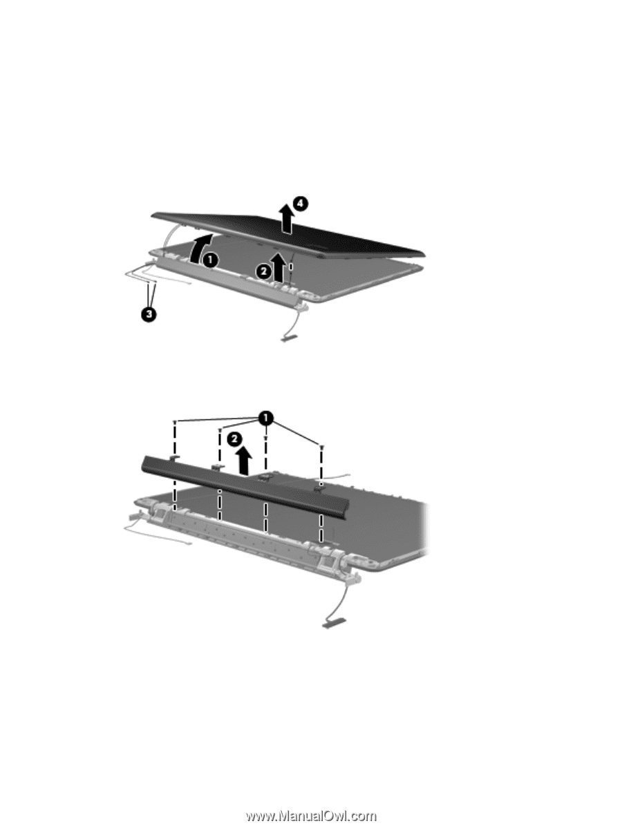
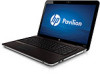
5. Turn the display assembly upside down, with the bottom toward you. 6. Lift and release the bottom of the display enclosure (1). 7. Disconnect the display logo cable (2) from the display panel cable. 8. Route the webcam cable and antenna cables (3) through the hinge channel. 9. Remove the display enclosure (4). The display enclosure is available using spare part number 605330-001. 10. If it is necessary to remove the hinge cover, remove the four Phillips PM2.5×5.0 screws (1) that secure the hinge cover to the display assembly, and then remove the cover (2). The hinge cover is available using spare part number 605336-001. 11. If it is necessary to replace the webcam/microphone module, remove the Phillips PM2.0×4.0 screw (1) that secures the module to the display bezel. 12. Release the webcam/microphone module (2) as far as the webcam/microphone module cable allows. 76 Chapter 4 Removal and replacement procedures
-
 1
1 -
2
-
3
-
4
-
5
-
6
-
7
-
8
-
9
-
10
-
11
-
12
-
13
-
14
-
15
-
16
-
17
-
18
-
19
-
20
-
21
-
22
-
23
-
24
-
25
-
26
-
27
-
28
-
29
-
30
-
31
-
32
-
33
-
34
-
35
-
36
-
37
-
38
-
39
-
40
-
41
-
42
-
43
-
44
-
45
-
46
-
47
-
48
-
49
-
50
-
51
-
52
-
53
-
54
-
55
-
56
-
57
-
58
-
59
-
60
-
61
-
62
-
63
-
64
-
65
-
66
-
67
-
68
-
69
-
70
-
71
-
72
-
73
-
74
-
75
-
76
-
77
-
78
-
79
-
80
-
 81
81 -
 82
82 -
 83
83 -
 84
84 -
 85
85 -
 86
86 -
 87
87 -
 88
88 -
 89
89 -
 90
90 -
 91
91 -
92
-
93
-
94
-
95
-
96
-
97
-
98
-
99
-
100
-
101
-
102
-
103
-
104
-
105
-
106
-
107
-
108
-
109
-
110
-
111
-
112
-
113
-
114
-
115
-
116
-
117
-
118
-
119
-
120
-
121
-
122
-
123
-
124
-
125
-
126
-
127
-
128
-
129
-
130
-
131
-
132
-
133
-
134
-
135
-
136
-
137
-
138
-
139
-
140
-
141
-
142
-
143
-
144
-
145
-
146
-
147
-
148
-
149
-
150
 |
 |