HP Pavilion dv7-5000 HP Pavilion dv7 Entertainment PC - Maintenance and Servic - Page 95
Remove the system board, that secure the system board to the base
 |
View all HP Pavilion dv7-5000 manuals
Add to My Manuals
Save this manual to your list of manuals |
Page 95 highlights
Remove the system board: 1. Disconnect the following cables from the system board: (1) USB board cable (2) Power connector cable (3) Subwoofer cable (4) Speaker cable 2. Remove the two Phillips PM2.5×5.0 screws (1) that secure the system board to the base enclosure. 3. Lift up on the right side of the system board until it is at approximately a 45-degree angle (2), and then lift the system board to the right and up and out of the base enclosure (3). Reverse this procedure to install the system board. Component replacement procedures 85
-
 1
1 -
2
-
3
-
4
-
5
-
6
-
7
-
8
-
9
-
10
-
11
-
12
-
13
-
14
-
15
-
16
-
17
-
18
-
19
-
20
-
21
-
22
-
23
-
24
-
25
-
26
-
27
-
28
-
29
-
30
-
31
-
32
-
33
-
34
-
35
-
36
-
37
-
38
-
39
-
40
-
41
-
42
-
43
-
44
-
45
-
46
-
47
-
48
-
49
-
50
-
51
-
52
-
53
-
54
-
55
-
56
-
57
-
58
-
59
-
60
-
61
-
62
-
63
-
64
-
65
-
66
-
67
-
68
-
69
-
70
-
71
-
72
-
73
-
74
-
75
-
76
-
77
-
78
-
79
-
80
-
81
-
82
-
83
-
84
-
85
-
86
-
87
-
88
-
89
-
 90
90 -
 91
91 -
 92
92 -
 93
93 -
 94
94 -
 95
95 -
 96
96 -
 97
97 -
 98
98 -
 99
99 -
 100
100 -
101
-
102
-
103
-
104
-
105
-
106
-
107
-
108
-
109
-
110
-
111
-
112
-
113
-
114
-
115
-
116
-
117
-
118
-
119
-
120
-
121
-
122
-
123
-
124
-
125
-
126
-
127
-
128
-
129
-
130
-
131
-
132
-
133
-
134
-
135
-
136
-
137
-
138
-
139
-
140
-
141
-
142
-
143
-
144
-
145
-
146
-
147
-
148
-
149
-
150
 |
 |
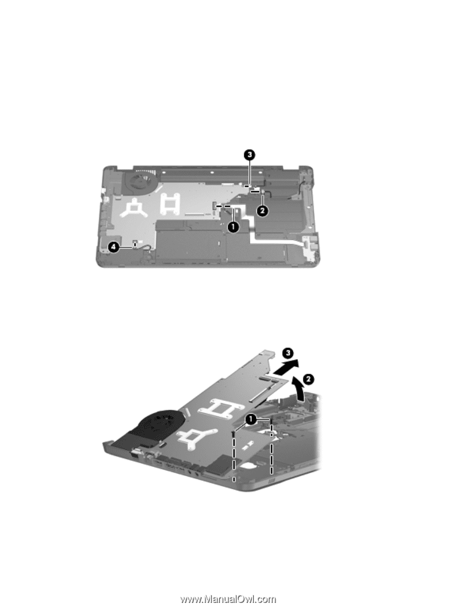
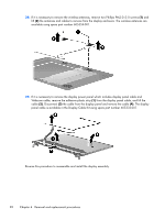
Remove the system board:
1.
Disconnect the following cables from the system board:
(1)
USB board cable
(2)
Power connector cable
(3)
Subwoofer cable
(4)
Speaker cable
2.
Remove the two Phillips PM2.5×5.0 screws
(1)
that secure the system board to the base
enclosure.
3.
Lift up on the right side of the system board until it is at approximately a 45-degree angle
(2)
, and
then lift the system board to the right and up and out of the base enclosure
(3)
.
Reverse this procedure to install the system board.
Component replacement procedures
85