HP Presario F500 Compaq Presario F500 and G6000 Notebook PC - Maintenance and - Page 119
DVD-RW and CD-RW Combo Drive, Display Screw Kit, spare part - wireless driver
 |
View all HP Presario F500 manuals
Add to My Manuals
Save this manual to your list of manuals |
Page 119 highlights
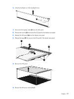
removal 47 spare part number 15, 20, 47 Display Screw Kit, spare part number 15, 20 display specifications 68 drive light 6 drivers, reinstalling 93 drives, boot order 66 drives, preventing damage 23 DVD-RW and CD-RW Combo Drive precautions 23 removal 36 spare part number 13, 17, 20, 36 specifications 70 DVD±RW and CD-RW Double-Layer Combo Drive precautions 23 removal 36 spare part number 13, 17, 21, 36 specifications 70 DVD±RW and CD-RW SuperMulti Double-Layer Combo Drive with LightScribe spare part number 13, 17, 21, 36 G graphics, product description 1 grounding equipment and methods 26 H hard drive precautions 23 product description 2 removal 30 spare part numbers 13, 17, 20, 21, 30 specifications 69 hard drive bay 9 hard drive cover illustrated 16 removal 30 hard drive self test 66 headphone jack location 6 pin assignments 97 headset, spare part number 18, 19 hinges illustrated 15 removal 47 spare part number 15, 20, 47 E electrostatic discharge 24 enhanced SATA support 66 Ethernet, product description 2 external monitor port location 8 pin assignments 98 F fan/heat sink assembly removal 58 spare part number 12, 20, 58 feet locations 32 spare part number 13, 20, 32 fingerprint reader 62 fn key 5 front components 6 function keys 5 I I/O address specifications 73 infrared emitter, spare part number 18 interrupt specifications 72 inverter illustrated 15 removal 46 spare part number 15, 20, 47 J jacks audio-in 6 audio-out 6 headphone 6 microphone 6 modem 8 network 8 RJ-11 8 RJ-45 8 S-Video-out 8 K keyboard product description 3 removal 40 spare part numbers 12, 21, 40 keyboard components 5 keypad keys 5 keys arrow 5 caps lock 5 fn 5 function 5 num lock 5 Windows applications 5 Windows logo 5 L language support 63, 66 left-side components 8 lights battery 6 drive 6 power 6 wireless 6 Logo Kit, spare part number 21 M Main menu 65 mass storage devices, spare part numbers 17 memory map specifications 75 memory module product description 1 removal 32 spare part numbers 13, 20, 21, 32 memory module compartment 9 memory module compartment cover illustrated 16 removal 33 microphone jack location 6 pin assignments 97 model name 1 modem jack location 8 pin assignments 99 Index 111
-
 1
1 -
2
-
3
-
4
-
5
-
6
-
7
-
8
-
9
-
10
-
11
-
12
-
13
-
14
-
15
-
16
-
17
-
18
-
19
-
20
-
21
-
22
-
23
-
24
-
25
-
26
-
27
-
28
-
29
-
30
-
31
-
32
-
33
-
34
-
35
-
36
-
37
-
38
-
39
-
40
-
41
-
42
-
43
-
44
-
45
-
46
-
47
-
48
-
49
-
50
-
51
-
52
-
53
-
54
-
55
-
56
-
57
-
58
-
59
-
60
-
61
-
62
-
63
-
64
-
65
-
66
-
67
-
68
-
69
-
70
-
71
-
72
-
73
-
74
-
75
-
76
-
77
-
78
-
79
-
80
-
81
-
82
-
83
-
84
-
85
-
86
-
87
-
88
-
89
-
90
-
91
-
92
-
93
-
94
-
95
-
96
-
97
-
98
-
99
-
100
-
101
-
102
-
103
-
104
-
105
-
106
-
107
-
108
-
109
-
110
-
111
-
112
-
113
-
 114
114 -
 115
115 -
 116
116 -
 117
117 -
 118
118 -
 119
119 -
 120
120 -
 121
121 -
 122
122
 |
 |