HP Presario F500 Compaq Presario F500 and G6000 Notebook PC - Maintenance and - Page 64
by sliding it away from the top cover at an angle.
 |
View all HP Presario F500 manuals
Add to My Manuals
Save this manual to your list of manuals |
Page 64 highlights
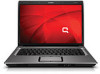
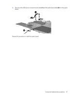
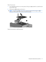
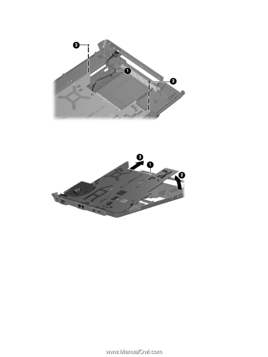
2. Remove the two Phillips PM2.5×4.0 screws (2) that secure the system board to the base enclosure. 3. Use the optical drive connector (1) to lift the right side of the system board (2) until it rests at an angle. 4. Remove the system board (3) by sliding it away from the top cover at an angle. 5. If it is necessary to replace the USB/power connector board cable or the audio board cable, turn the system board upside down, with the front toward you. 56 Chapter 4 Removal and replacement procedures
-
 1
1 -
2
-
3
-
4
-
5
-
6
-
7
-
8
-
9
-
10
-
11
-
12
-
13
-
14
-
15
-
16
-
17
-
18
-
19
-
20
-
21
-
22
-
23
-
24
-
25
-
26
-
27
-
28
-
29
-
30
-
31
-
32
-
33
-
34
-
35
-
36
-
37
-
38
-
39
-
40
-
41
-
42
-
43
-
44
-
45
-
46
-
47
-
48
-
49
-
50
-
51
-
52
-
53
-
54
-
55
-
56
-
57
-
58
-
 59
59 -
 60
60 -
 61
61 -
 62
62 -
 63
63 -
 64
64 -
 65
65 -
 66
66 -
 67
67 -
 68
68 -
 69
69 -
70
-
71
-
72
-
73
-
74
-
75
-
76
-
77
-
78
-
79
-
80
-
81
-
82
-
83
-
84
-
85
-
86
-
87
-
88
-
89
-
90
-
91
-
92
-
93
-
94
-
95
-
96
-
97
-
98
-
99
-
100
-
101
-
102
-
103
-
104
-
105
-
106
-
107
-
108
-
109
-
110
-
111
-
112
-
113
-
114
-
115
-
116
-
117
-
118
-
119
-
120
-
121
-
122
 |
 |
2
.
Remove the two Phillips PM2.5×4.0 screws
(2)
that secure the system board to the base enclosure.
3
.
Use the optical drive connector
(1)
to lift the right side of the system board
(2)
until it rests at an
angle.
4
.
Remove the system board
(3)
by sliding it away from the top cover at an angle.
5
.
If it is necessary to replace the USB/power connector board cable or the audio board cable, turn
the system board upside down, with the front toward you.
56
Chapter
4
Removal and replacement procedures