HP Presario F500 Compaq Presario F500 and G6000 Notebook PC - Maintenance and - Page 60
Release the audio board, that secure the audio board to the computer.
 |
View all HP Presario F500 manuals
Add to My Manuals
Save this manual to your list of manuals |
Page 60 highlights
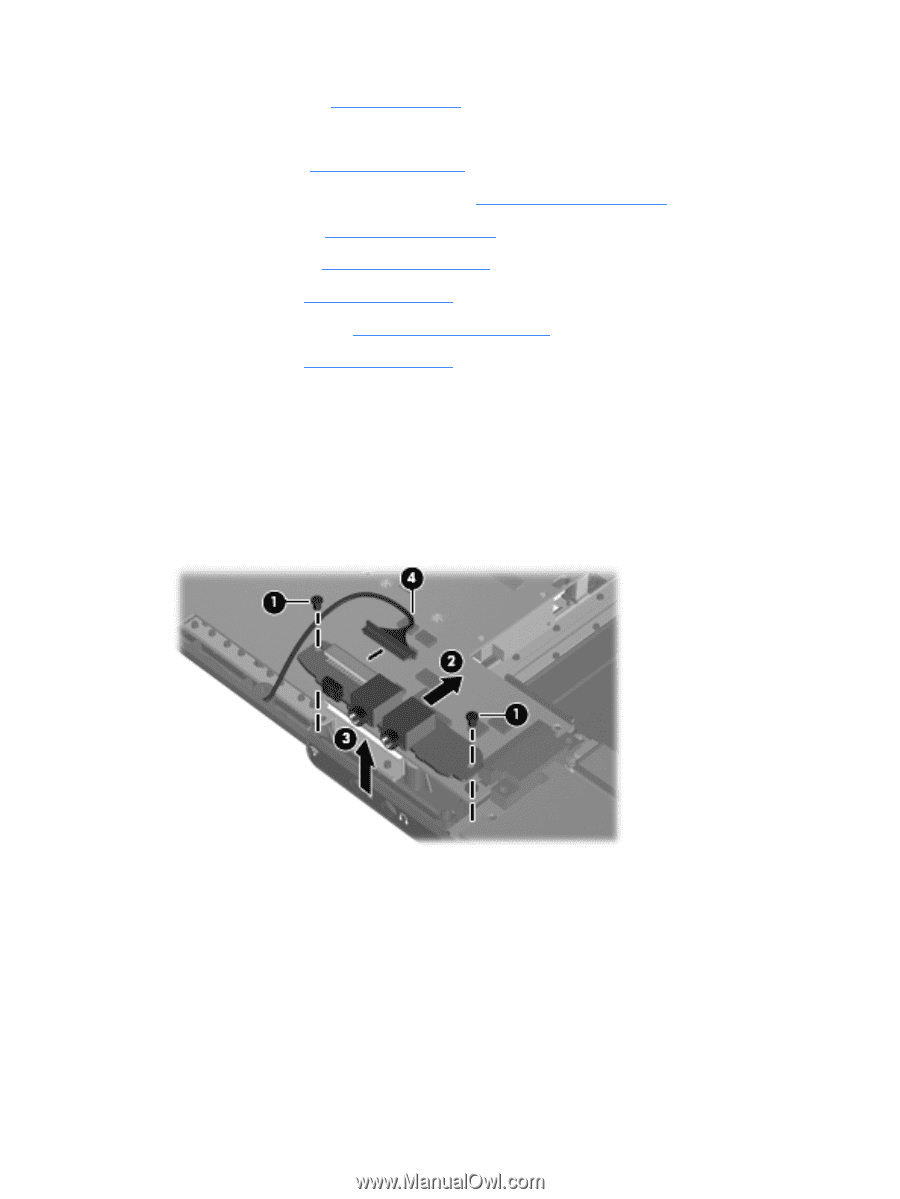
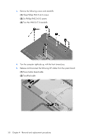
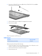
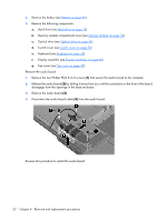
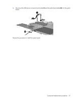
4. Remove the battery (see Battery on page 29). 5. Remove the following components: a. Hard drive (see Hard drive on page 30) b. Memory module compartment cover (see Memory module on page 32) c. Optical drive (see Optical drive on page 36) d. Switch cover (see Switch cover on page 38) e. Keyboard (see Keyboard on page 40) f. Display assembly (see Display assembly on page 44) g. Top cover (see Top cover on page 49) Remove the audio board: 1. Remove the two Phillips PM2.5×5.0 screws (1) that secure the audio board to the computer. 2. Release the audio board (2) by sliding it away from you until the connectors on the front of the board disengage from the openings in the base enclosure. 3. Remove the audio board (3). 4. Disconnect the audio board cable (4) from the audio board. Reverse this procedure to install the audio board. 52 Chapter 4 Removal and replacement procedures
-
 1
1 -
2
-
3
-
4
-
5
-
6
-
7
-
8
-
9
-
10
-
11
-
12
-
13
-
14
-
15
-
16
-
17
-
18
-
19
-
20
-
21
-
22
-
23
-
24
-
25
-
26
-
27
-
28
-
29
-
30
-
31
-
32
-
33
-
34
-
35
-
36
-
37
-
38
-
39
-
40
-
41
-
42
-
43
-
44
-
45
-
46
-
47
-
48
-
49
-
50
-
51
-
52
-
53
-
54
-
 55
55 -
 56
56 -
 57
57 -
 58
58 -
 59
59 -
 60
60 -
 61
61 -
 62
62 -
 63
63 -
 64
64 -
 65
65 -
66
-
67
-
68
-
69
-
70
-
71
-
72
-
73
-
74
-
75
-
76
-
77
-
78
-
79
-
80
-
81
-
82
-
83
-
84
-
85
-
86
-
87
-
88
-
89
-
90
-
91
-
92
-
93
-
94
-
95
-
96
-
97
-
98
-
99
-
100
-
101
-
102
-
103
-
104
-
105
-
106
-
107
-
108
-
109
-
110
-
111
-
112
-
113
-
114
-
115
-
116
-
117
-
118
-
119
-
120
-
121
-
122
 |
 |