HP Presario F500 Compaq Presario F500 and G6000 Notebook PC - Maintenance and - Page 66
Fan/heat sink assembly
 |
View all HP Presario F500 manuals
Add to My Manuals
Save this manual to your list of manuals |
Page 66 highlights
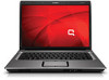
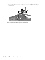
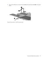
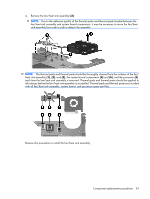
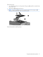
Fan/heat sink assembly Description Fan/heat sink assembly (includes thermal paste and thermal pads) Spare part number 431450-001 NOTE: To properly ventilate the computer, allow at least a 7.6-cm (3-inch) clearance on the right side and rear panel of the computer. The computer uses an electric fan for ventilation. The fan is controlled by a temperature sensor and is designed to turn on automatically when high temperature conditions exist. These conditions are affected by high external temperatures, system power consumption, power management/battery conservation configurations, battery fast charging, and software applications. Exhaust air is displaced through the ventilation grill located on the left side of the computer. Before removing the fan/heat sink assembly, follow these steps: 1. Shut down the computer. If you are unsure whether the computer is off or in Hibernation, turn the computer on, and then shut it down through the operating system. 2. Disconnect all external devices connected to the computer. 3. Disconnect the power cord. 4. Remove the battery (see Battery on page 29). 5. Remove the following components: a. Hard drive (see Hard drive on page 30) b. Memory module compartment cover (see Memory module on page 32) c. Optical drive (see Optical drive on page 36) d. Switch cover (see Switch cover on page 38) e. Keyboard (see Keyboard on page 40) f. Display assembly (see Display assembly on page 44) g. Top cover (see Top cover on page 49) h. System board (see System board on page 55) Remove the fan/heat sink assembly: 1. Turn the system board upside down, with the external monitor port toward you. 2. Disconnect the fan cable (1) from the system board. 3. Loosen the five Phillips PM2.5×5.0 screws (2) that secure the fan/heat sink assembly to the system board. 58 Chapter 4 Removal and replacement procedures
-
 1
1 -
2
-
3
-
4
-
5
-
6
-
7
-
8
-
9
-
10
-
11
-
12
-
13
-
14
-
15
-
16
-
17
-
18
-
19
-
20
-
21
-
22
-
23
-
24
-
25
-
26
-
27
-
28
-
29
-
30
-
31
-
32
-
33
-
34
-
35
-
36
-
37
-
38
-
39
-
40
-
41
-
42
-
43
-
44
-
45
-
46
-
47
-
48
-
49
-
50
-
51
-
52
-
53
-
54
-
55
-
56
-
57
-
58
-
59
-
60
-
 61
61 -
 62
62 -
 63
63 -
 64
64 -
 65
65 -
 66
66 -
 67
67 -
 68
68 -
 69
69 -
 70
70 -
 71
71 -
72
-
73
-
74
-
75
-
76
-
77
-
78
-
79
-
80
-
81
-
82
-
83
-
84
-
85
-
86
-
87
-
88
-
89
-
90
-
91
-
92
-
93
-
94
-
95
-
96
-
97
-
98
-
99
-
100
-
101
-
102
-
103
-
104
-
105
-
106
-
107
-
108
-
109
-
110
-
111
-
112
-
113
-
114
-
115
-
116
-
117
-
118
-
119
-
120
-
121
-
122
 |
 |