HP Presario F500 Compaq Presario F500 and G6000 Notebook PC - Maintenance and - Page 63
System board, Switch cover see
 |
View all HP Presario F500 manuals
Add to My Manuals
Save this manual to your list of manuals |
Page 63 highlights
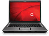
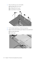
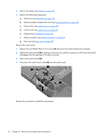
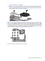
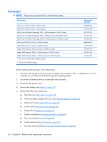
System board Description System board Spare part number 442875-001 When replacing the system board, be sure that the following components are removed from the defective system board and installed on the replacement system board: ● Memory module (see Memory module on page 32) ● RTC battery (see RTC battery on page 34) ● WLAN module (see WLAN module on page 35) ● Fan/heat sink assembly (see Fan/heat sink assembly on page 58) ● Processor (see Processor on page 60) Before removing the system board, follow these steps: 1. Shut down the computer. If you are unsure whether the computer is off or in Hibernation, turn the computer on, and then shut it down through the operating system. 2. Disconnect all external devices connected to the computer. 3. Disconnect the power cord. 4. Remove the battery (see Battery on page 29). 5. Remove the following components: a. Hard drive (see Hard drive on page 30) b. Optical drive (see Optical drive on page 36) c. Switch cover (see Switch cover on page 38) d. Keyboard (see Keyboard on page 40) e. Display assembly (see Display assembly on page 44) f. Top cover (see Top cover on page 49) g. USB/power connector board (see USB/power connector board on page 53) Remove the system board: 1. Remove the USB/power connector board cable (1) from the clips in the base enclosure. Component replacement procedures 55
-
 1
1 -
2
-
3
-
4
-
5
-
6
-
7
-
8
-
9
-
10
-
11
-
12
-
13
-
14
-
15
-
16
-
17
-
18
-
19
-
20
-
21
-
22
-
23
-
24
-
25
-
26
-
27
-
28
-
29
-
30
-
31
-
32
-
33
-
34
-
35
-
36
-
37
-
38
-
39
-
40
-
41
-
42
-
43
-
44
-
45
-
46
-
47
-
48
-
49
-
50
-
51
-
52
-
53
-
54
-
55
-
56
-
57
-
 58
58 -
 59
59 -
 60
60 -
 61
61 -
 62
62 -
 63
63 -
 64
64 -
 65
65 -
 66
66 -
 67
67 -
 68
68 -
69
-
70
-
71
-
72
-
73
-
74
-
75
-
76
-
77
-
78
-
79
-
80
-
81
-
82
-
83
-
84
-
85
-
86
-
87
-
88
-
89
-
90
-
91
-
92
-
93
-
94
-
95
-
96
-
97
-
98
-
99
-
100
-
101
-
102
-
103
-
104
-
105
-
106
-
107
-
108
-
109
-
110
-
111
-
112
-
113
-
114
-
115
-
116
-
117
-
118
-
119
-
120
-
121
-
122
 |
 |