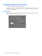
HP Presario F500 Compaq Presario F500 and G6000 Notebook PC - Maintenance and - Page 41
to prevent incorrect installation into the, Memory modules are designed with a notch
 |
View all HP Presario F500 manuals
Add to My Manuals
Save this manual to your list of manuals |
Page 41 highlights
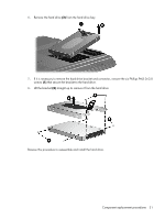
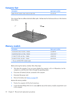
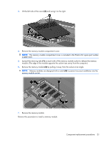
3. Lift the left side of the cover (2) and swing it to the right. 4. Remove the memory module compartment cover. NOTE: The memory module compartment cover is included in the Plastics Kit, spare part number 442891-001. 5. Spread the retaining tabs (1) on each side of the memory module socket to release the memory module. (The edge of the module opposite the socket rises away from the computer.) 6. Remove the memory module (2) by pulling it away from the socket at an angle. NOTE: Memory modules are designed with a notch (3) to prevent incorrect installation into the memory module socket. 7. Remove the memory module. Reverse this procedure to install a memory module. Component replacement procedures 33
-
 1
1 -
2
-
3
-
4
-
5
-
6
-
7
-
8
-
9
-
10
-
11
-
12
-
13
-
14
-
15
-
16
-
17
-
18
-
19
-
20
-
21
-
22
-
23
-
24
-
25
-
26
-
27
-
28
-
29
-
30
-
31
-
32
-
33
-
34
-
35
-
 36
36 -
 37
37 -
 38
38 -
 39
39 -
 40
40 -
 41
41 -
 42
42 -
 43
43 -
 44
44 -
 45
45 -
 46
46 -
47
-
48
-
49
-
50
-
51
-
52
-
53
-
54
-
55
-
56
-
57
-
58
-
59
-
60
-
61
-
62
-
63
-
64
-
65
-
66
-
67
-
68
-
69
-
70
-
71
-
72
-
73
-
74
-
75
-
76
-
77
-
78
-
79
-
80
-
81
-
82
-
83
-
84
-
85
-
86
-
87
-
88
-
89
-
90
-
91
-
92
-
93
-
94
-
95
-
96
-
97
-
98
-
99
-
100
-
101
-
102
-
103
-
104
-
105
-
106
-
107
-
108
-
109
-
110
-
111
-
112
-
113
-
114
-
115
-
116
-
117
-
118
-
119
-
120
-
121
-
122
 |
 |
3
.
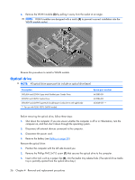
Lift the left side of the cover
(2)
and swing it to the right.
4
.
Remove the memory module compartment cover.
NOTE:
The memory module compartment cover is included in the Plastics Kit, spare part number
442891-001.
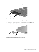
5
.
Spread the retaining tabs
(1)
on each side of the memory module socket to release the memory
module. (The edge of the module opposite the socket rises away from the computer.)
6
.
Remove the memory module
(2)
by pulling it away from the socket at an angle.
NOTE:
Memory modules are designed with a notch
(3)
to prevent incorrect installation into the
memory module socket.
7
.
Remove the memory module.
Reverse this procedure to install a memory module.
Component replacement procedures
33