HP Pro 2080 Maintenance & Service Guide: HP Pro 2000/2080 Business PC - Page 46
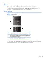
Cable Connections
 |
View all HP Pro 2080 manuals
Add to My Manuals
Save this manual to your list of manuals |
Page 46 highlights
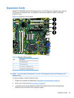
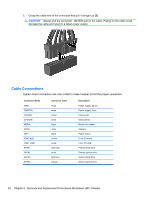
2. Grasp the cable end of the connector and pull it straight up (2). CAUTION: Always pull the connector - NEVER pull on the cable. Pulling on the cable could damage the cable and result in a failed power supply. Cable Connections System board connectors are color-coded to make it easier to find the proper connection. Connector Name PWR PWRCPU CHFAN1 CPUFAN MEDIA SPKR JFP1 FRNT AUD FRNT USB1 SATA1 SATA2 SATA3 SATA4 Connector Color white white brown white black white black yellow white dark blue white light blue orange Description Power supply, 24-pin Power supply, 4-pin Chassis fan Heat sink fan Media card reader Speaker Power switch Front I/O audio Front I/O USB Primary hard drive Primary optical drive Second hard drive Second optical drive 38 Chapter 6 Removal and Replacement Procedures Microtower (MT) Chassis
-
 1
1 -
2
-
3
-
4
-
5
-
6
-
7
-
8
-
9
-
10
-
11
-
12
-
13
-
14
-
15
-
16
-
17
-
18
-
19
-
20
-
21
-
22
-
23
-
24
-
25
-
26
-
27
-
28
-
29
-
30
-
31
-
32
-
33
-
34
-
35
-
36
-
37
-
38
-
39
-
40
-
 41
41 -
 42
42 -
 43
43 -
 44
44 -
 45
45 -
 46
46 -
 47
47 -
 48
48 -
 49
49 -
 50
50 -
 51
51 -
52
-
53
-
54
-
55
-
56
-
57
-
58
-
59
-
60
-
61
-
62
-
63
-
64
-
65
-
66
-
67
-
68
-
69
-
70
-
71
-
72
-
73
-
74
-
75
-
76
-
77
-
78
-
79
-
80
-
81
-
82
-
83
-
84
-
85
-
86
-
87
-
88
-
89
-
90
-
91
-
92
-
93
-
94
-
95
-
96
-
97
-
98
-
99
-
100
-
101
-
102
-
103
-
104
-
105
-
106
-
107
-
108
-
109
-
110
-
111
-
112
-
113
-
114
-
115
-
116
-
117
-
118
-
119
-
120
-
121
-
122
-
123
-
124
-
125
 |
 |