HP Pro 2080 Maintenance & Service Guide: HP Pro 2000/2080 Business PC - Page 64
Heat sink assembly
 |
View all HP Pro 2080 manuals
Add to My Manuals
Save this manual to your list of manuals |
Page 64 highlights
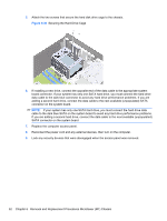
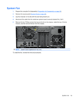
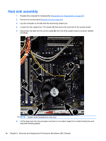
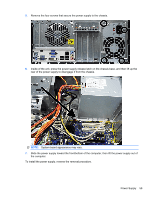
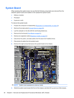
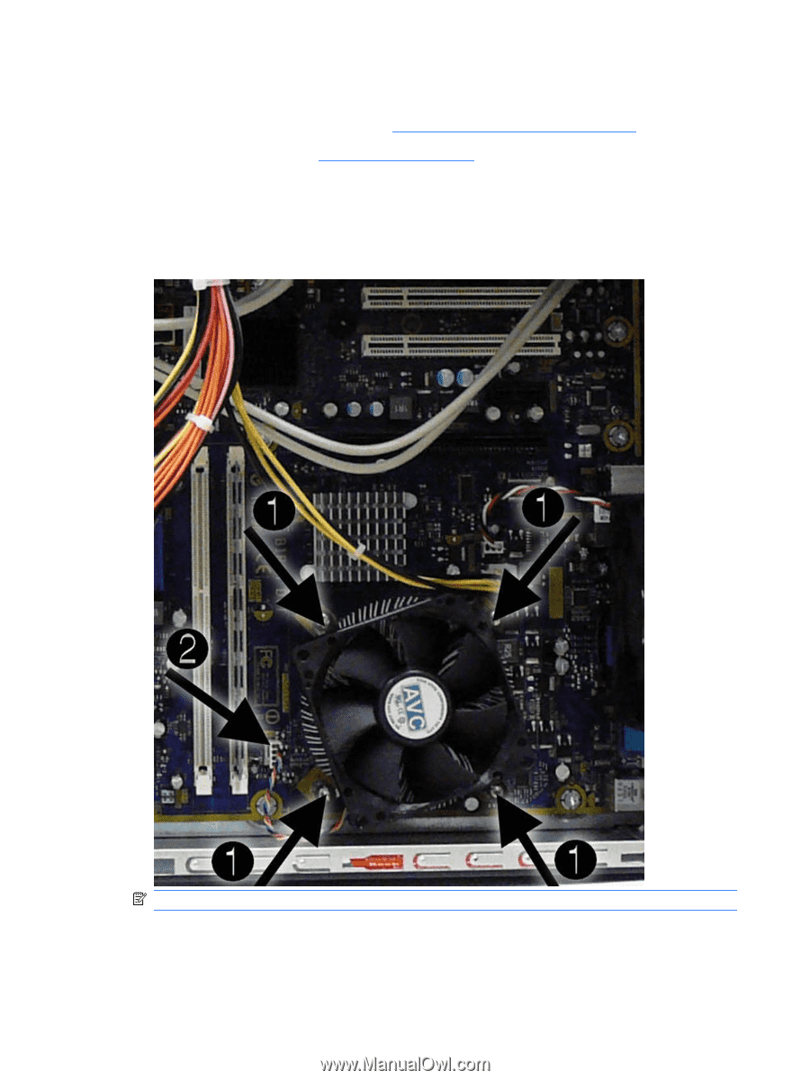
Heat sink assembly 1. Prepare the computer for disassembly (Preparation for Disassembly on page 25). 2. Remove the access panel (Access Panel on page 26). 3. Lay the computer on its side with the rear facing toward you. 4. Loosen the four captive torx T15 screws (1) that secure the heat sink to the system board. 5. Disconnect the heat sink fan control cable (2) from the white system board connector labeled CPUFAN. NOTE: System board appearance may vary. 6. Lift the heat sink from the processor and set it on its side to keep from contaminating the work area with thermal grease. 56 Chapter 6 Removal and Replacement Procedures Microtower (MT) Chassis
-
 1
1 -
2
-
3
-
4
-
5
-
6
-
7
-
8
-
9
-
10
-
11
-
12
-
13
-
14
-
15
-
16
-
17
-
18
-
19
-
20
-
21
-
22
-
23
-
24
-
25
-
26
-
27
-
28
-
29
-
30
-
31
-
32
-
33
-
34
-
35
-
36
-
37
-
38
-
39
-
40
-
41
-
42
-
43
-
44
-
45
-
46
-
47
-
48
-
49
-
50
-
51
-
52
-
53
-
54
-
55
-
56
-
57
-
58
-
 59
59 -
 60
60 -
 61
61 -
 62
62 -
 63
63 -
 64
64 -
 65
65 -
 66
66 -
 67
67 -
 68
68 -
 69
69 -
70
-
71
-
72
-
73
-
74
-
75
-
76
-
77
-
78
-
79
-
80
-
81
-
82
-
83
-
84
-
85
-
86
-
87
-
88
-
89
-
90
-
91
-
92
-
93
-
94
-
95
-
96
-
97
-
98
-
99
-
100
-
101
-
102
-
103
-
104
-
105
-
106
-
107
-
108
-
109
-
110
-
111
-
112
-
113
-
114
-
115
-
116
-
117
-
118
-
119
-
120
-
121
-
122
-
123
-
124
-
125
 |
 |
Heat sink assembly
1.
Prepare the computer for disassembly (
Preparation for Disassembly
on page
25
).
2.
Remove the access panel (
Access Panel
on page
26
).
3.
Lay the computer on its side with the rear facing toward you.
4.
Loosen the four captive torx T15 screws
(1)
that secure the heat sink to the system board.
5.
Disconnect the heat sink fan control cable
(2)
from the white system board connector labeled
CPUFAN.
NOTE:
System board appearance may vary.
6.
Lift the heat sink from the processor and set it on its side to keep from contaminating the work
area with thermal grease.
56
Chapter 6
Removal and Replacement Procedures Microtower (MT) Chassis