HP Pro 2080 Maintenance & Service Guide: HP Pro 2000/2080 Business PC - Page 52
Removing an External 3.5-inch Drive, CAUTION
 |
View all HP Pro 2080 manuals
Add to My Manuals
Save this manual to your list of manuals |
Page 52 highlights
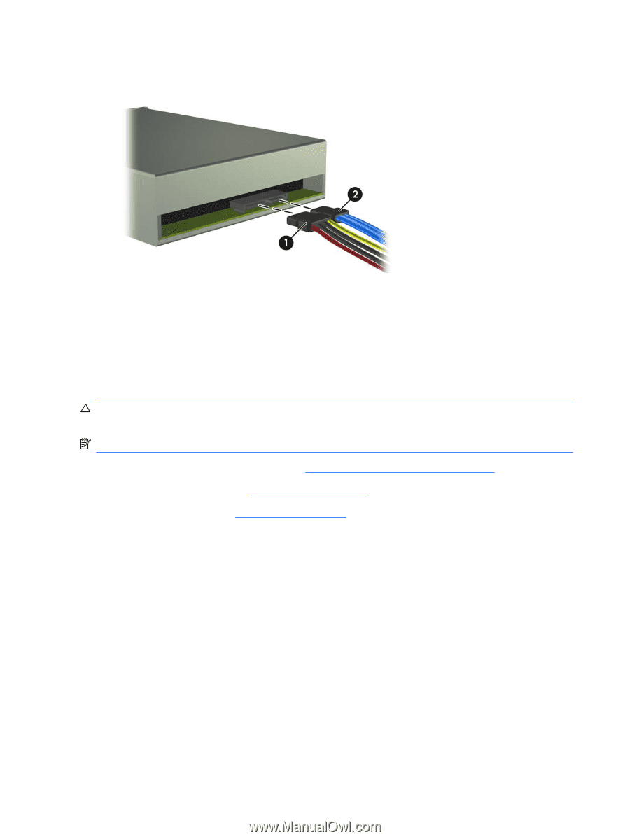
9. Connect the power cable (1) and data cable (2) to the rear of the optical drive. Figure 6-19 Connecting the Power and Data Cables 10. Replace the front bezel and access panel. 11. Reconnect the power cord and turn on the computer. 12. Lock any security devices that were disengaged when the access panel was removed. The system automatically recognizes the drive and reconfigures the computer. Removing an External 3.5-inch Drive CAUTION: All removable media should be taken out of a drive before removing the drive from the computer. NOTE: The 3.5-inch drive bay may contain a media card reader. 1. Prepare the computer for disassembly (Preparation for Disassembly on page 25). 2. Remove the access panel (Access Panel on page 26). 3. Remove the front bezel (Front Bezel on page 27). 4. Disconnect the drive cables. a. If you are removing a diskette drive (available on some models only), disconnect the data cable and power cable from the back of the drive. b. If you are removing a media card reader, disconnect the USB cable from the system board. 44 Chapter 6 Removal and Replacement Procedures Microtower (MT) Chassis
-
 1
1 -
2
-
3
-
4
-
5
-
6
-
7
-
8
-
9
-
10
-
11
-
12
-
13
-
14
-
15
-
16
-
17
-
18
-
19
-
20
-
21
-
22
-
23
-
24
-
25
-
26
-
27
-
28
-
29
-
30
-
31
-
32
-
33
-
34
-
35
-
36
-
37
-
38
-
39
-
40
-
41
-
42
-
43
-
44
-
45
-
46
-
 47
47 -
 48
48 -
 49
49 -
 50
50 -
 51
51 -
 52
52 -
 53
53 -
 54
54 -
 55
55 -
 56
56 -
 57
57 -
58
-
59
-
60
-
61
-
62
-
63
-
64
-
65
-
66
-
67
-
68
-
69
-
70
-
71
-
72
-
73
-
74
-
75
-
76
-
77
-
78
-
79
-
80
-
81
-
82
-
83
-
84
-
85
-
86
-
87
-
88
-
89
-
90
-
91
-
92
-
93
-
94
-
95
-
96
-
97
-
98
-
99
-
100
-
101
-
102
-
103
-
104
-
105
-
106
-
107
-
108
-
109
-
110
-
111
-
112
-
113
-
114
-
115
-
116
-
117
-
118
-
119
-
120
-
121
-
122
-
123
-
124
-
125
 |
 |