HP Pro 2080 Maintenance & Service Guide: HP Pro 2000/2080 Business PC - Page 62
Power Switch/LED Assembly
 |
View all HP Pro 2080 manuals
Add to My Manuals
Save this manual to your list of manuals |
Page 62 highlights
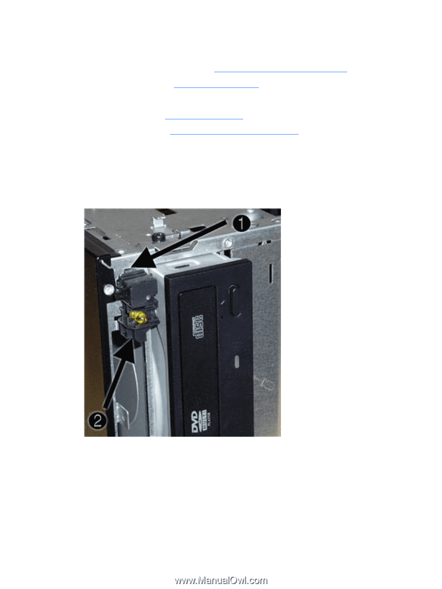
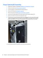
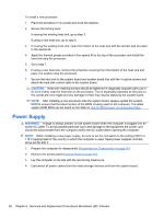
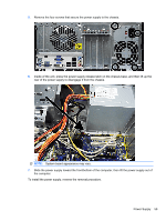
Power Switch/LED Assembly 1. Prepare the computer for disassembly (Preparation for Disassembly on page 25). 2. Remove the access panel (Access Panel on page 26). 3. Lay the computer on its side with the front facing toward you. 4. Remove the front bezel (Front Bezel on page 27). 5. Remove the optical drive (Removing an Optical Drive on page 42). 6. Disconnect the braided cables from the black system board connector labeled JFP1. 7. Remove the cable from the clips in the optical drive cage. 8. Press the tab on the top of the switch holder (1) to disengage it from the chassis, lift the switch upward to disengage the tab at the bottom of the switch (2) from the chassis, and then pull the power switch away from the chassis while guiding the wires through the hole in the chassis. To install the power switch/LED assembly, reverse the removal procedures. 54 Chapter 6 Removal and Replacement Procedures Microtower (MT) Chassis
-
 1
1 -
2
-
3
-
4
-
5
-
6
-
7
-
8
-
9
-
10
-
11
-
12
-
13
-
14
-
15
-
16
-
17
-
18
-
19
-
20
-
21
-
22
-
23
-
24
-
25
-
26
-
27
-
28
-
29
-
30
-
31
-
32
-
33
-
34
-
35
-
36
-
37
-
38
-
39
-
40
-
41
-
42
-
43
-
44
-
45
-
46
-
47
-
48
-
49
-
50
-
51
-
52
-
53
-
54
-
55
-
56
-
 57
57 -
 58
58 -
 59
59 -
 60
60 -
 61
61 -
 62
62 -
 63
63 -
 64
64 -
 65
65 -
 66
66 -
 67
67 -
68
-
69
-
70
-
71
-
72
-
73
-
74
-
75
-
76
-
77
-
78
-
79
-
80
-
81
-
82
-
83
-
84
-
85
-
86
-
87
-
88
-
89
-
90
-
91
-
92
-
93
-
94
-
95
-
96
-
97
-
98
-
99
-
100
-
101
-
102
-
103
-
104
-
105
-
106
-
107
-
108
-
109
-
110
-
111
-
112
-
113
-
114
-
115
-
116
-
117
-
118
-
119
-
120
-
121
-
122
-
123
-
124
-
125
 |
 |