HP Pro 2080 Maintenance & Service Guide: HP Pro 2000/2080 Business PC - Page 66
Power Supply
 |
View all HP Pro 2080 manuals
Add to My Manuals
Save this manual to your list of manuals |
Page 66 highlights
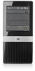
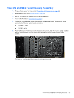
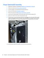
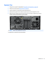
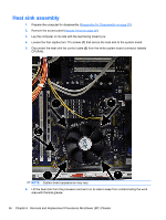
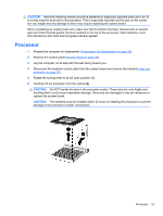
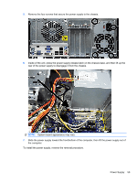
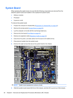
To install a new processor: 1. Place the processor in its socket and close the retainer. 2. Secure the locking lever. If reusing the existing heat sink, go to step 3. If using a new heat sink, go to step 6. 3. If reusing the existing heat sink, clean the bottom of the heat sink with the alcohol pad provided in the spares kit. 4. Apply the thermal grease provided in the spares kit to the top of the processor and install the heat sink atop the processor. 5. Go to step 7. 6. If using a new heat sink, remove the protective covering from the bottom of the heat sink and place it in position atop the processor. 7. Secure the heat sink to the system board and system board tray with the 4 captive screws and attach the heat sink control cable to the system board. CAUTION: Heat sink retaining screws should be tightened in diagonally opposite pairs (as in an X) to evenly seat the heat sink on the processor. This is especially important as the pins on the socket are very fragile and any damage to them may require replacing the system board. NOTE: After installing a new processor onto the system board, always update the system ROM to ensure that the latest version of the BIOS is being used on the computer. The latest system ROM BIOS can be found on the Web at: http:\\h18000.www1.hp.com/support/files. Power Supply WARNING! Voltage is always present on the system board when the computer is plugged into an active AC outlet. To avoid possible personal injury and damage to the equipment the power cord should be disconnected from the computer and/or the AC outlet before opening the computer. NOTE: When installing a new power supply, be sure to set the red switch to the setting (230 V or 115 V) appropriate for the country in which the computer is used. Spare power supplies normally arrive set for 230 V. 1. Prepare the computer for disassembly (Preparation for Disassembly on page 25). 2. Remove the access panel (Access Panel on page 26). 3. Lay the computer on its side with the rear facing toward you. 4. Disconnect all power cables from the mass storage devices and from the system board. 58 Chapter 6 Removal and Replacement Procedures Microtower (MT) Chassis
-
 1
1 -
2
-
3
-
4
-
5
-
6
-
7
-
8
-
9
-
10
-
11
-
12
-
13
-
14
-
15
-
16
-
17
-
18
-
19
-
20
-
21
-
22
-
23
-
24
-
25
-
26
-
27
-
28
-
29
-
30
-
31
-
32
-
33
-
34
-
35
-
36
-
37
-
38
-
39
-
40
-
41
-
42
-
43
-
44
-
45
-
46
-
47
-
48
-
49
-
50
-
51
-
52
-
53
-
54
-
55
-
56
-
57
-
58
-
59
-
60
-
 61
61 -
 62
62 -
 63
63 -
 64
64 -
 65
65 -
 66
66 -
 67
67 -
 68
68 -
 69
69 -
 70
70 -
 71
71 -
72
-
73
-
74
-
75
-
76
-
77
-
78
-
79
-
80
-
81
-
82
-
83
-
84
-
85
-
86
-
87
-
88
-
89
-
90
-
91
-
92
-
93
-
94
-
95
-
96
-
97
-
98
-
99
-
100
-
101
-
102
-
103
-
104
-
105
-
106
-
107
-
108
-
109
-
110
-
111
-
112
-
113
-
114
-
115
-
116
-
117
-
118
-
119
-
120
-
121
-
122
-
123
-
124
-
125
 |
 |