HP Rp5700 Hardware Reference Guide - HP rp5700
HP Rp5700 - Point of Sale System Manual
 |
UPC - 884420470731
View all HP Rp5700 manuals
Add to My Manuals
Save this manual to your list of manuals |
HP Rp5700 manual content summary:
- HP Rp5700 | Hardware Reference Guide - HP rp5700 - Page 1
Hardware Reference Guide HP rp5700 - HP Rp5700 | Hardware Reference Guide - HP rp5700 - Page 2
that is protected by copyright. No part of this document may be photocopied, reproduced, or translated to another language without the prior written consent of Hewlett-Packard Company. Hardware Reference Guide HP rp5700 Second Edition (July 2007) First Edition (April 2007) Document Part - HP Rp5700 | Hardware Reference Guide - HP rp5700 - Page 3
About This Book This guide provides basic information for upgrading this computer model. WARNING! Text set off in this manner indicates that failure to follow directions could result in bodily harm or loss of life. CAUTION: Text - HP Rp5700 | Hardware Reference Guide - HP rp5700 - Page 4
iv About This Book ENWW - HP Rp5700 | Hardware Reference Guide - HP rp5700 - Page 5
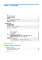
...4 Using the Windows Logo Key 5 Special Mouse Functions ...6 Serial Number Location ...6 2 Hardware Upgrades Serviceability Features ...7 Warnings and Cautions ...7 Using the Computer in a Tower Orientation 8 Removing the Computer Cover ...10 Replacing the Computer Cover ...11 Removing the Bezel - HP Rp5700 | Hardware Reference Guide - HP rp5700 - Page 6
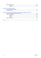
Padlock ...57 Appendix F Electrostatic Discharge Preventing Electrostatic Damage ...58 Grounding Methods ...58 Appendix G Computer Operating Guidelines, Routine Care and Shipping Preparation Computer Operating Guidelines and Routine Care 59 Optical Drive Precautions ...60 Operation ...60 Cleaning - HP Rp5700 | Hardware Reference Guide - HP rp5700 - Page 7
The HP Point of Sale System rp5700 features may vary depending on the model. For a complete listing of the hardware and software installed in the computer, run the diagnostic utility (included on some computer models only). Instructions for using the utility are provided in the Troubleshooting Guide - HP Rp5700 | Hardware Reference Guide - HP rp5700 - Page 8
(some models)1 5 Dual-State Power Button 2 Optical Drive Activity Light 6 Power On Light 3 Optical Power On Light is normally green when the power is on. If it is flashing red, there is a problem with the computer and it is displaying a diagnostic code. Refer to the Troubleshooting Guide - HP Rp5700 | Hardware Reference Guide - HP rp5700 - Page 9
for powered audio devices (green) Line-In Audio Connector (blue) NOTE: Arrangement and number of connectors may vary by model. If a PCI graphics card is installed, the connectors on the card and the system board may be used at the same time. Some settings may need to be changed in Computer Setup - HP Rp5700 | Hardware Reference Guide - HP rp5700 - Page 10
, End, and Page Down. 3 Status Lights Indicate the status of the computer and keyboard settings (Num Lock, Caps Lock, and Scroll Lock). 4 Numeric functions in other software applications. 8 Windows Logo Keys1 Used to open the Start menu in Microsoft Windows. Used in combination with other keys - HP Rp5700 | Hardware Reference Guide - HP rp5700 - Page 11
Logo Key + Tab Displays or hides the Start menu Displays the Desktop Minimizes all open applications Undoes Minimize All Launches My Computer Launches Find Document Launches Find Computer Launches Windows Help Locks the computer if you are connected to a network domain, or allows you to switch - HP Rp5700 | Hardware Reference Guide - HP rp5700 - Page 12
applications you are using. Serial Number Location Each computer has a unique serial number and product ID number located on the back of the computer. Keep these numbers available for use when contacting customer service for assistance. Figure 1-2 Serial Number and Product ID Location 6 Chapter - HP Rp5700 | Hardware Reference Guide - HP rp5700 - Page 13
performing upgrades be sure to carefully read all of the applicable instructions, cautions, and warnings in this guide. WARNING! To reduce the risk of personal injury from electrical shock, hot surfaces, or fire: Disconnect the power cord from the wall outlet and allow the internal system components - HP Rp5700 | Hardware Reference Guide - HP rp5700 - Page 14
HP logo plate on the front bezel is adjustable for either desktop or tower orientation. 1. Remove/disengage any security devices that prohibit opening the computer. 2. Remove all removable media, such as compact discs, from the computer. 3. Turn off the computer properly through the operating system - HP Rp5700 | Hardware Reference Guide - HP rp5700 - Page 15
on the stand is pointing toward the front of the computer. Figure 2-1 Changing from Desktop to Tower Orientation 10. Reconnect the power cord and any external devices, then turn on the computer. 11. Lock any security devices that were disengaged when the computer cover was removed. CAUTION: Do not - HP Rp5700 | Hardware Reference Guide - HP rp5700 - Page 16
devices that prohibit opening the computer. 2. Remove all removable media, such as compact discs, from the computer. 3. Turn off the computer properly through the operating system, then turn off any external devices. 4. Disconnect the power cord from the power outlet and disconnect any external - HP Rp5700 | Hardware Reference Guide - HP rp5700 - Page 17
Replacing the Computer Cover Place the computer cover on the chassis about 1.3 cm (½ inch) in front of the final position and slide it back into place until it locks. Figure 2-3 Replacing the Computer Cover ENWW Replacing the Computer Cover 11 - HP Rp5700 | Hardware Reference Guide - HP rp5700 - Page 18
keeping the bezel blank bowed out, push in on the end of the bezel blank nearest to the power button until the end of the bezel blank is released. Remove the bezel blank from the computer cover. Figure 2-5 Removing a Bezel Blank 4. Replace the computer cover. 12 Chapter 2 Hardware Upgrades ENWW - HP Rp5700 | Hardware Reference Guide - HP rp5700 - Page 19
populated with at least one preinstalled DIMM. To achieve the maximum memory support, you can populate the system board with up to 8 GB of memory configured in a highperforming dual channel mode. DDR2-SDRAM DIMMs For proper system operation, the DDR2-SDRAM DIMMs must be: ● industry-standard 240-pin - HP Rp5700 | Hardware Reference Guide - HP rp5700 - Page 20
two 256MB DIMMs and Channel B is populated with one 512MB DIMM, the system will operate in dual channel mode. ● The system will operate in flex mode if the total memory capacity of the DIMMs in Channel A is not equal to the total memory capacity of the DIMMs in Channel B. In flex mode, the channel - HP Rp5700 | Hardware Reference Guide - HP rp5700 - Page 21
or removing memory modules. Regardless of the power-on state, voltage is always supplied to the memory modules as long as the computer is plugged into an active AC outlet. Adding or removing memory modules while voltage is present may cause irreparable damage to the memory modules or system board - HP Rp5700 | Hardware Reference Guide - HP rp5700 - Page 22
8. Raise the drive cage to the upright position. Figure 2-7 Rotating the Drive Cage Up 9. Rotate the fan duct out of the chassis. Figure 2-8 Rotating the Fan Duct 16 Chapter 2 Hardware Upgrades ENWW - HP Rp5700 | Hardware Reference Guide - HP rp5700 - Page 23
supply to the upright position (2). Figure 2-9 Releasing and Rotating the Power Supply 11. Open both latches of the memory module socket (1), and insert the memory module into the socket (2). NOTE: A memory module can be installed in only one way. Match the notch on the module with the tab on the - HP Rp5700 | Hardware Reference Guide - HP rp5700 - Page 24
Reconnect the power cord and any external devices, then turn on the computer. The computer should automatically recognize the additional memory when you turn on the computer. 20. Lock any security devices that were disengaged when the computer cover was removed. 18 Chapter 2 Hardware Upgrades ENWW - HP Rp5700 | Hardware Reference Guide - HP rp5700 - Page 25
NOTE: The computer only supports the use of normal (or non-reversed) layout ADD2 (Advanced Digital Display 2) adapter cards inserted into the SDVO (Serial Digital Video Output) connector on the platform's system board. ADD2 cards are used to give multi-monitor capabilities to the integrated graphics - HP Rp5700 | Hardware Reference Guide - HP rp5700 - Page 26
card: 1. Remove/disengage any security devices that prohibit opening the computer. 2. Remove all removable media, such as compact discs, from the computer. 3. Turn off the computer properly through the operating system, then turn off any external devices. 4. Disconnect the power cord from the power - HP Rp5700 | Hardware Reference Guide - HP rp5700 - Page 27
it from the chassis frame. Be sure not to scrape the card against the other components. Figure 2-14 Removing a PCI Express x1 Expansion Card 9. Store the removed card in anti-static packaging. 10. If you are not installing a new expansion card, install an expansion slot cover to close the open slot - HP Rp5700 | Hardware Reference Guide - HP rp5700 - Page 28
in the expansion card slot. 12. Close the slot cover retainer. Figure 2-16 Closing the Slot Cover Retainer NOTE: The slot cover retainer is secured in place by the computer cover. 13. Replace the computer cover. 14. If the computer was on a stand, replace the stand. 15. Reconnect the power cord and - HP Rp5700 | Hardware Reference Guide - HP rp5700 - Page 29
were disengaged when the computer cover was removed. 17. Reconfigure the computer, if necessary. Refer to the Computer Setup (F10) Utility Guide on the Documentation and Diagnostics CD for instructions about using Computer Setup. Installing and Removing a PCI Card in the Riser Card You can install - HP Rp5700 | Hardware Reference Guide - HP rp5700 - Page 30
If you are installing an expansion card in a vacant socket, remove the appropriate expansion slot cover on the back of the chassis. Pull the slot cover straight out toward the left side of the chassis. Figure 2-19 Removing a PCI Riser Card Expansion Slot Cover 24 Chapter 2 Hardware Upgrades ENWW - HP Rp5700 | Hardware Reference Guide - HP rp5700 - Page 31
riser. Be sure not to scrape the card against the other components. NOTE: Before removing an installed expansion card, disconnect any cables that may be attached to the expansion card. Figure 2-20 Removing a Standard PCI Expansion Card 11. Store the removed card in anti-static packaging. 12. If you - HP Rp5700 | Hardware Reference Guide - HP rp5700 - Page 32
cover. 15. Connect external cables to the installed card, if needed. Connect internal cables to the system board, if needed. 16. Return the power supply to the down position until it locks. 17. Replace the computer cover. 18. If the computer was on a stand, replace the stand. 19. Reconnect the - HP Rp5700 | Hardware Reference Guide - HP rp5700 - Page 33
any security devices that were disengaged when the computer cover was removed. 21. Reconfigure the computer, if necessary. Refer to the Computer Setup (F10) Utility Guide on the Documentation and Diagnostics CD for instructions about using Computer Setup. Drive Positions Figure 2-23 Drive Positions - HP Rp5700 | Hardware Reference Guide - HP rp5700 - Page 34
only. The other four guide screws are black M3 metric screws used for all other drives. CAUTION: To prevent loss of work and damage to the computer or drive: If you are inserting or removing a drive, shut down the operating system properly, turn off the computer, and unplug the power cord. Do not - HP Rp5700 | Hardware Reference Guide - HP rp5700 - Page 35
as long as the system is plugged into an active AC outlet. You must disconnect the power cord to avoid damage to the internal components of the computer. 5. If the computer is on a stand, remove the computer from the stand. 6. Remove the computer cover. 7. Disconnect the power cable (1) and data - HP Rp5700 | Hardware Reference Guide - HP rp5700 - Page 36
(2). Figure 2-25 Removing the Optical Drive NOTE: When replacing a drive, transfer the four guide screws from the old remove the bezel blank covering the 5.25-inch drive bay. 2. Install two M3 metric guide screws in the lower holes on each side of the drive. HP has provided four extra M3 metric guide - HP Rp5700 | Hardware Reference Guide - HP rp5700 - Page 37
SATA 1. 6. Replace the computer cover. 7. If the computer was on a stand, replace the stand. 8. Reconnect the power cord and any external devices, then turn on the computer. 9. Lock any security devices that were disengaged when the computer cover was removed. The system automatically recognizes the - HP Rp5700 | Hardware Reference Guide - HP rp5700 - Page 38
initially set up the computer to restore the operating system, software drivers, and any software applications that were preinstalled on the computer. If you do not have this CD set, create it now. Refer to the HP Backup and Recovery Manager User Guide in the Windows Start menu for more information - HP Rp5700 | Hardware Reference Guide - HP rp5700 - Page 39
and power cable (2) from the back of the primary hard drive. Figure 2-31 Disconnecting the Primary Hard Drive Data and Power Cables CAUTION: Never crease or bend a SATA data cable tighter than a 30 mm (1.18 in) radius. A sharp bend can break the internal wires. ENWW Installing and Removing Drives - HP Rp5700 | Hardware Reference Guide - HP rp5700 - Page 40
drive cage (2). Figure 2-32 Removing the Primary Hard Drive To install a primary hard drive: 1. Install two 6-32 standard guide screws in the lower holes need a Torx T-15 screwdriver to remove and re-install the guide screws. HP has provided four extra 6-32 standard guide screws on the front of the - HP Rp5700 | Hardware Reference Guide - HP rp5700 - Page 41
NOTE: If the system has only one SATA hard drive, the data cable must be connected to the dark blue connector labeled SATA 0 on the system board to avoid any hard drive performance problems. Figure 2-35 Connecting the Primary Hard Drive Data and Power Cables ENWW Installing and Removing Drives 35 - HP Rp5700 | Hardware Reference Guide - HP rp5700 - Page 42
system board as long as the system is plugged into an active AC outlet. You must disconnect the power cord to avoid damage to the internal components of the computer. 5. If the computer is on a stand, remove the computer from the stand. 6. Remove the computer cover. 36 Chapter 2 Hardware Upgrades - HP Rp5700 | Hardware Reference Guide - HP rp5700 - Page 43
the drive cage to the upright position. Figure 2-37 Rotating the Drive Cage Up 8. Press the latch release on the front of the power supply (1), and then raise the power supply to the upright position (2) Figure 2-38 Releasing and Rotating the Power Supply ENWW Installing and Removing Drives 37 - HP Rp5700 | Hardware Reference Guide - HP rp5700 - Page 44
cable (1) and data cable (2) from the back of the secondary hard drive. Figure 2-39 Disconnecting the Secondary Hard Drive Power and Data Cables 10. Press the release catch on the right side of the secondary hard drive (1), slide the drive forward until it stops, then - HP Rp5700 | Hardware Reference Guide - HP rp5700 - Page 45
replacing the secondary hard drive, transfer the four screws from the old drive to the new one. You will need a Torx T-15 screwdriver to remove and re-install the guide screws. HP has provided four extra 6-32 standard guide screws on the front of the chassis, under the front bezel. The 6-32 standard - HP Rp5700 | Hardware Reference Guide - HP rp5700 - Page 46
the computer. 6. Replace the computer cover. 7. If the computer was on a stand, replace the stand. 8. Reconnect the power cord and any external devices, then turn on the computer. 9. Lock any security devices that were disengaged when the computer cover was removed. 40 Chapter 2 Hardware Upgrades - HP Rp5700 | Hardware Reference Guide - HP rp5700 - Page 47
A Specifications Desktop Dimensions Height 3.94 in 10 cm Width 13.40 in 34 may be limited by the type and number of options installed. Heat Dissipation Maximum 1260 BTU/hr 317 kg-cal/hr Typical (idle) 388 BTU/hr 98 kg-cal/hr Power Supply 115V 230V Operating Voltage Range1 90-264 - HP Rp5700 | Hardware Reference Guide - HP rp5700 - Page 48
Card: 1. Remove/disengage any security devices that prohibit opening the computer. 2. Remove all removable media, such as compact discs, from the computer. 3. Turn off the computer properly through the operating system, then turn off any external devices. 4. Disconnect the power cord from the power - HP Rp5700 | Hardware Reference Guide - HP rp5700 - Page 49
as the system is plugged into an active AC outlet. You must disconnect the power cord to avoid damage to the internal components of the computer. 5. If the computer is on a stand, remove the computer from the stand. 6. Remove the computer cover. 7. Remove the USB PlusPower Expansion Card. a. Press - HP Rp5700 | Hardware Reference Guide - HP rp5700 - Page 50
harness to the system board (1) and the expansion card (2). Connect the power cable to the expansion card (3). Figure B-5 Connecting System Board and Power Cables to the USB PlusPower Expansion Card c. Return the power supply to the down position until it locks. 9. Replace the computer cover. 10. If - HP Rp5700 | Hardware Reference Guide - HP rp5700 - Page 51
serial ports, COM 1 and COM 2, are standard on the computer. Some models have a powered serial port expansion card installed that supplies two additional powered serial ports, COM 3 and COM 4. Figure C-1 Powered Serial Ports Item Description 1 COM 1 (yellow) 2 COM 2 (teal) 3 COM 3 (teal - HP Rp5700 | Hardware Reference Guide - HP rp5700 - Page 52
Removing the Powered Serial Port Caps These powered serial ports have been protected with plastic caps. Turn off the computer and remove the caps before connecting powered serial Point of Sale devices. Figure C-2 Removing the Powered Serial Port Caps 46 Appendix C Powered Serial Ports ENWW - HP Rp5700 | Hardware Reference Guide - HP rp5700 - Page 53
The serial ports on the HP Point of Sale System computer can be configured as standard (non-powered) serial ports or powered serial ports. Some Point of Sale devices use a powered serial port. If the serial port is configured as a powered port, devices that support a powered serial interface do not - HP Rp5700 | Hardware Reference Guide - HP rp5700 - Page 54
Name COM 4 COM 3 To configure power to the serial ports: 1. Remove/disengage any security devices that prohibit opening the computer. 2. Remove all removable media, such as compact discs, from the computer. 3. Turn off the computer properly through the operating system, then turn off any external - HP Rp5700 | Hardware Reference Guide - HP rp5700 - Page 55
3 or COM 4 serial port configuration, remove the Powered Serial Port Expansion Card. a. Locate the Powered Serial Port Expansion Card in the upper socket of the PC riser. Disconnect the power and system board cables attached to the expansion card. b. Hold the PCI card at each end, and carefully rock - HP Rp5700 | Hardware Reference Guide - HP rp5700 - Page 56
Reconnect the power cord and any external devices, then turn on the computer. 14. Lock any security devices that were disengaged when the computer cover was removed. 15. If the serial ports are configured in powered mode, connect the powered Point of Sale device. 50 Appendix C Powered Serial Ports - HP Rp5700 | Hardware Reference Guide - HP rp5700 - Page 57
Table C-1 Configuring Serial Port Power ENWW Configuring Power to a Serial Port 51 - HP Rp5700 | Hardware Reference Guide - HP rp5700 - Page 58
52 Appendix C Powered Serial Ports ENWW - HP Rp5700 | Hardware Reference Guide - HP rp5700 - Page 59
. You must disconnect the power cord to avoid damage to the internal components of the computer. 5. If the computer is on a stand, remove the computer from the stand. 6. Remove the computer cover. 7. Locate the battery and battery holder on the system board. NOTE: On some computer models, it may be - HP Rp5700 | Hardware Reference Guide - HP rp5700 - Page 60
type of battery holder on the system board, complete the following instructions to replace the battery. Type 1 a. Lift the battery out of its holder. Figure D-1 Removing a Coin Cell Battery (Type 1) b. Slide the replacement battery into position, positive side up. The battery holder automatically - HP Rp5700 | Hardware Reference Guide - HP rp5700 - Page 61
on power to the computer. 12. Reset the date and time, your passwords, and any special system setups using Computer Setup. Refer to the Computer Setup (F10) Utility Guide on the Documentation and Diagnostics CD. 13. Lock any security devices that were disengaged when the computer cover was removed - HP Rp5700 | Hardware Reference Guide - HP rp5700 - Page 62
information on data security features, refer to the Computer Setup (F10) Utility Guide and the Desktop Management Guide on the Documentation and Diagnostics CD and the HP ProtectTools Security Manager Guide (some models) at http://www.hp.com. Installing a Security Lock The security locks displayed - HP Rp5700 | Hardware Reference Guide - HP rp5700 - Page 63
Padlock Figure E-2 Installing a Padlock ENWW Installing a Security Lock 57 - HP Rp5700 | Hardware Reference Guide - HP rp5700 - Page 64
damage system boards grounded surface before removing them from their to a grounded workstation or computer chassis. Wrist straps are HP authorized dealer, reseller, or service provider. NOTE: For more information on static electricity, contact an HP authorized dealer, reseller, or service - HP Rp5700 | Hardware Reference Guide - HP rp5700 - Page 65
guidelines listed above will still apply. ● Keep liquids away from the computer and keyboard. ● Never cover the ventilation slots on the monitor with any type of material. ● Install or enable power management functions of the operating system or other software, including sleep states. ● Turn off the - HP Rp5700 | Hardware Reference Guide - HP rp5700 - Page 66
hard drive locks automatically when the system power is turned off. 2. Remove and store all removable media. 3. Turn off the computer and external devices. 4. Disconnect the power cord from the electrical outlet, then from the computer. 5. Disconnect the system components and external devices from - HP Rp5700 | Hardware Reference Guide - HP rp5700 - Page 67
memory installing 13 populating sockets 14 specifications 13 monitor connector 3 mouse connector 3 special functions 6 ENWW N network connector 3 O optical drive cleaning 60 defined 2 precautions 60 removing 29 P parallel connector 3 PCI card 19, 25 PCI Express card 19 PCI Express x1 card 21 power - HP Rp5700 | Hardware Reference Guide - HP rp5700 - Page 68
shipping preparation 60 specifications computer 41 memory 13 T tower orientation 8 U unlocking computer cover 56 USB ports rear panel 3 V ventilation guidelines 59 W Web site HP ProtectTools Security Manager Guide 56 HP recycling programs 53 Safety & Comfort Guide 7 Windows Logo key 5 62 Index
-
 1
1 -
 2
2 -
 3
3 -
 4
4 -
 5
5 -
 6
6 -
 7
7 -
8
-
9
-
10
-
11
-
12
-
13
-
14
-
15
-
16
-
17
-
18
-
19
-
20
-
21
-
22
-
23
-
24
-
25
-
26
-
27
-
28
-
29
-
30
-
31
-
32
-
33
-
34
-
35
-
36
-
37
-
38
-
39
-
40
-
41
-
42
-
43
-
44
-
45
-
46
-
47
-
48
-
49
-
50
-
51
-
52
-
53
-
54
-
55
-
56
-
57
-
58
-
59
-
60
-
61
-
62
-
63
-
64
-
65
-
66
-
67
-
68
 |
 |

Hardware Reference Guide
HP rp5700