HP Rp5700 Hardware Reference Guide - HP rp5700 - Page 37
CAUTION, Connecting the Optical Drive Power and Data Cables
 |
UPC - 884420470731
View all HP Rp5700 manuals
Add to My Manuals
Save this manual to your list of manuals |
Page 37 highlights
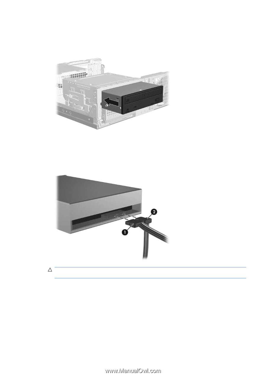
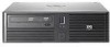
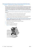
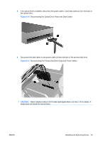
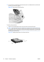
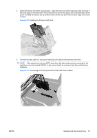
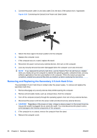
3. Align the guide screws on the drive with the slots on the chassis. Slide the drive into the optical drive bay all the way back until it locks. Figure 2-27 Installing the Optical Drive 4. Connect the power cable (1) and data cable (2) to the rear of the optical drive. Figure 2-28 Connecting the Optical Drive Power and Data Cables CAUTION: Never crease or bend a SATA data cable tighter than a 30 mm (1.18 in) radius. A sharp bend can break the internal wires. 5. Connect the other end of the SATA data cable to the white system board connector labeled SATA 1. 6. Replace the computer cover. 7. If the computer was on a stand, replace the stand. 8. Reconnect the power cord and any external devices, then turn on the computer. 9. Lock any security devices that were disengaged when the computer cover was removed. The system automatically recognizes the drive and reconfigures the computer. ENWW Installing and Removing Drives 31
-
 1
1 -
2
-
3
-
4
-
5
-
6
-
7
-
8
-
9
-
10
-
11
-
12
-
13
-
14
-
15
-
16
-
17
-
18
-
19
-
20
-
21
-
22
-
23
-
24
-
25
-
26
-
27
-
28
-
29
-
30
-
31
-
 32
32 -
 33
33 -
 34
34 -
 35
35 -
 36
36 -
 37
37 -
 38
38 -
 39
39 -
 40
40 -
 41
41 -
 42
42 -
43
-
44
-
45
-
46
-
47
-
48
-
49
-
50
-
51
-
52
-
53
-
54
-
55
-
56
-
57
-
58
-
59
-
60
-
61
-
62
-
63
-
64
-
65
-
66
-
67
-
68
 |
 |