HP Rp5700 Hardware Reference Guide - HP rp5700 - Page 56
C-8, Connecting System Board and Power Cables to the Powered Serial Port
 |
UPC - 884420470731
View all HP Rp5700 manuals
Add to My Manuals
Save this manual to your list of manuals |
Page 56 highlights
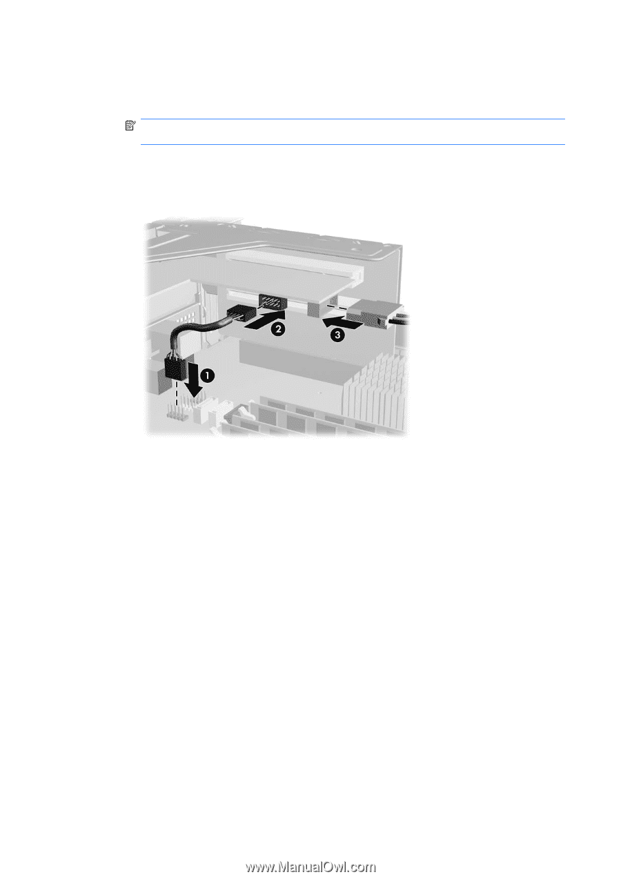
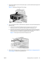
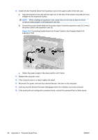
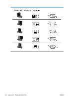
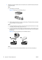
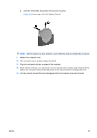
10. Install the new Powered Serial Port Expansion Card in the upper socket of the riser card. a. Align the bracket on the card with the open slot on the rear of the chassis and press the card straight into the expansion socket. NOTE: When installing an expansion card, press firmly on the card so that the whole connector seats properly in the expansion card slot. b. Connect the system board cables to the system board (1) and the expansion card (2). Connect the power cable to the expansion card (3). Figure C-8 Connecting System Board and Power Cables to the Powered Serial Port Expansion Card c. Return the power supply to the down position until it locks. 11. Replace the computer cover. 12. If the computer was on a stand, replace the stand. 13. Reconnect the power cord and any external devices, then turn on the computer. 14. Lock any security devices that were disengaged when the computer cover was removed. 15. If the serial ports are configured in powered mode, connect the powered Point of Sale device. 50 Appendix C Powered Serial Ports ENWW
-
 1
1 -
2
-
3
-
4
-
5
-
6
-
7
-
8
-
9
-
10
-
11
-
12
-
13
-
14
-
15
-
16
-
17
-
18
-
19
-
20
-
21
-
22
-
23
-
24
-
25
-
26
-
27
-
28
-
29
-
30
-
31
-
32
-
33
-
34
-
35
-
36
-
37
-
38
-
39
-
40
-
41
-
42
-
43
-
44
-
45
-
46
-
47
-
48
-
49
-
50
-
 51
51 -
 52
52 -
 53
53 -
 54
54 -
 55
55 -
 56
56 -
 57
57 -
 58
58 -
 59
59 -
 60
60 -
 61
61 -
62
-
63
-
64
-
65
-
66
-
67
-
68
 |
 |