HP Rp5700 Hardware Reference Guide - HP rp5700 - Page 55
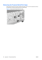
C-6, Removing the Powered Serial Port Expansion Card
 |
UPC - 884420470731
View all HP Rp5700 manuals
Add to My Manuals
Save this manual to your list of manuals |
Page 55 highlights
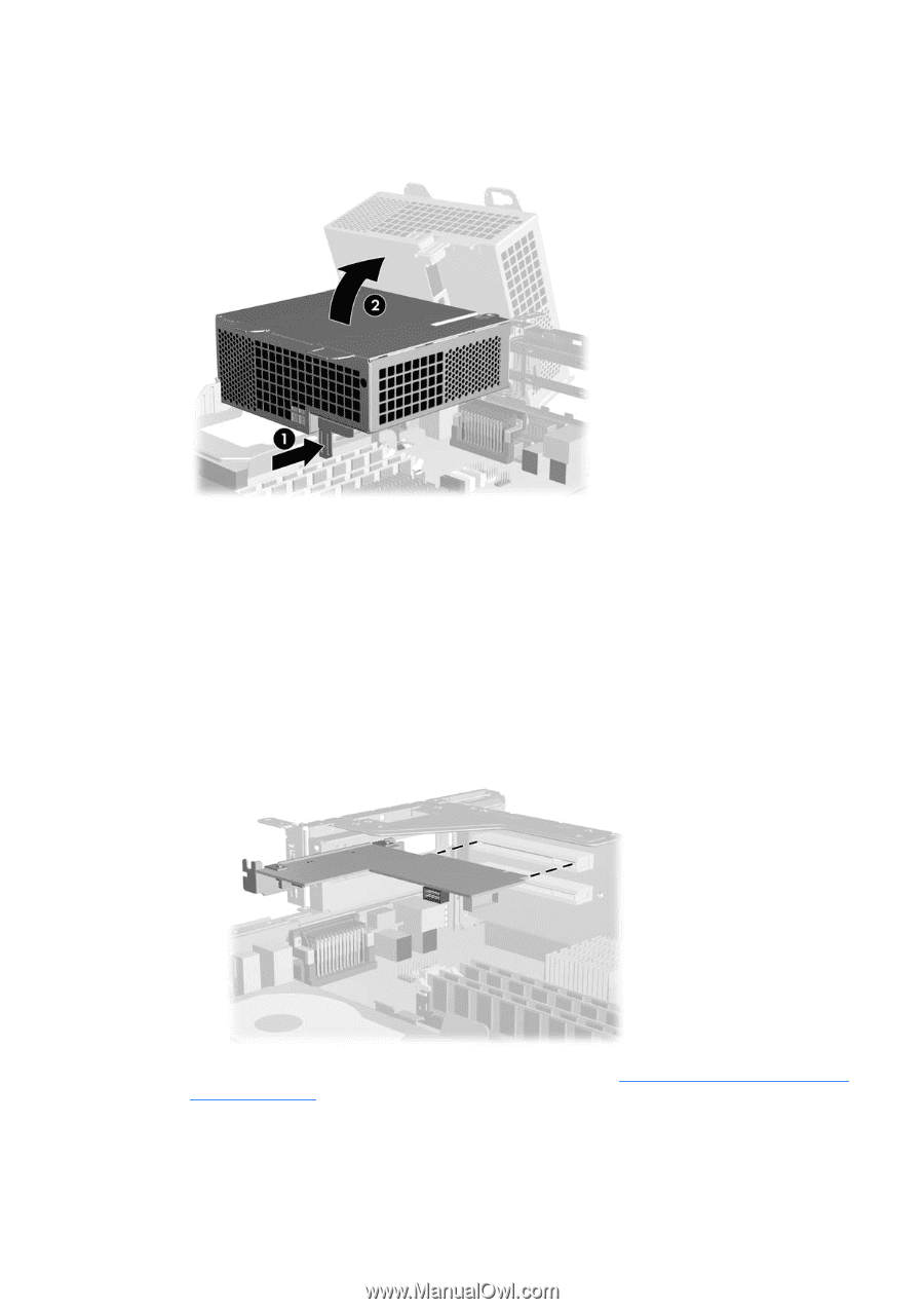
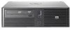
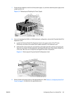
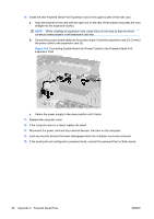
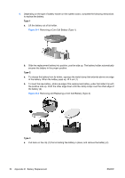
7. Press the latch release on the front of the power supply (1), and then raise the power supply to the upright position (2) Figure C-6 Releasing and Rotating the Power Supply 8. If you are changing the COM 3 or COM 4 serial port configuration, remove the Powered Serial Port Expansion Card. a. Locate the Powered Serial Port Expansion Card in the upper socket of the PC riser. Disconnect the power and system board cables attached to the expansion card. b. Hold the PCI card at each end, and carefully rock it back and forth until the connectors pull free from the socket. Pull the expansion card toward the left side of the chassis straight out of the riser. Be sure not to scrape the card against the other components. Figure C-7 Removing the Powered Serial Port Expansion Card 9. Place jumpers and jumper wires on the appropriate pins. (See Table C-1 Configuring Serial Port Power on page 51 to determine the appropriate pins.) ENWW Configuring Power to a Serial Port 49
-
 1
1 -
2
-
3
-
4
-
5
-
6
-
7
-
8
-
9
-
10
-
11
-
12
-
13
-
14
-
15
-
16
-
17
-
18
-
19
-
20
-
21
-
22
-
23
-
24
-
25
-
26
-
27
-
28
-
29
-
30
-
31
-
32
-
33
-
34
-
35
-
36
-
37
-
38
-
39
-
40
-
41
-
42
-
43
-
44
-
45
-
46
-
47
-
48
-
49
-
 50
50 -
 51
51 -
 52
52 -
 53
53 -
 54
54 -
 55
55 -
 56
56 -
 57
57 -
 58
58 -
 59
59 -
 60
60 -
61
-
62
-
63
-
64
-
65
-
66
-
67
-
68
 |
 |