HP Surestore 64 fw 05.01.00 and sw 07.01.00 - Director Product Manager - User - Page 84
Using the Port Card View, Symbols and Indicators, Port Card View, Enable Beaconing
 |
View all HP Surestore 64 manuals
Add to My Manuals
Save this manual to your list of manuals |
Page 84 highlights
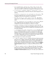
Monitoring and Managing the Director If you click the Enable Beaconing check box to add a check mark, the amber LED beacons (blinks) on the card that was the active card before switchover. Note: You must have maintenance authorization rights to access this feature. Using the Port Card View In the Hardware View, double-click a port card or right-click and choose Open Port Card View to see a detailed view of the port card. In the Port Card View, colored indicators reflect functions of the actual LEDs on the card. The table in the Port Card View displays the port operating state and vital product information. Symbols and Indicators The following figure illustrates the status symbols and LED indicators that may display on a port card in the Port Card View. 1 UPM 2 3 1 An amber LED (at the top of the card) that illuminates if any port fails or blinks if FRU beaconing is enabled. 2 A bank of amber and green LEDs above the ports. One amber LED and one green LED are associated with each port and indicate port status as follows: ■ The green LED illuminates (or blinks if there is active traffic) and the amber LED extinguishes to indicate normal port operation. ■ The amber LED illuminates and the green LED extinguishes to indicate a port failure. ■ Both LEDs extinguish to indicate a port is operational but not communicating with an N_Port (no cable attached, loss of light, port blocked, or link recovery in process). ■ The amber LED flashes and the green LED either remains on, extinguishes, or flashes to indicate a port is beaconing or running online diagnostics. 3 Four duplex LC connectors for attaching fiber optic cables. Figure 22: Port Card View 84 Director Product Manager User Guide
-
 1
1 -
2
-
3
-
4
-
5
-
6
-
7
-
8
-
9
-
10
-
11
-
12
-
13
-
14
-
15
-
16
-
17
-
18
-
19
-
20
-
21
-
22
-
23
-
24
-
25
-
26
-
27
-
28
-
29
-
30
-
31
-
32
-
33
-
34
-
35
-
36
-
37
-
38
-
39
-
40
-
41
-
42
-
43
-
44
-
45
-
46
-
47
-
48
-
49
-
50
-
51
-
52
-
53
-
54
-
55
-
56
-
57
-
58
-
59
-
60
-
61
-
62
-
63
-
64
-
65
-
66
-
67
-
68
-
69
-
70
-
71
-
72
-
73
-
74
-
75
-
76
-
77
-
78
-
 79
79 -
 80
80 -
 81
81 -
 82
82 -
 83
83 -
 84
84 -
 85
85 -
 86
86 -
 87
87 -
 88
88 -
 89
89 -
90
-
91
-
92
-
93
-
94
-
95
-
96
-
97
-
98
-
99
-
100
-
101
-
102
-
103
-
104
-
105
-
106
-
107
-
108
-
109
-
110
-
111
-
112
-
113
-
114
-
115
-
116
-
117
-
118
-
119
-
120
-
121
-
122
-
123
-
124
-
125
-
126
-
127
-
128
-
129
-
130
-
131
-
132
-
133
-
134
-
135
-
136
-
137
-
138
-
139
-
140
-
141
-
142
-
143
-
144
-
145
-
146
-
147
-
148
-
149
-
150
-
151
-
152
-
153
-
154
-
155
-
156
-
157
-
158
-
159
-
160
-
161
-
162
-
163
-
164
-
165
-
166
-
167
-
168
-
169
-
170
-
171
-
172
-
173
-
174
-
175
-
176
-
177
-
178
-
179
-
180
-
181
-
182
-
183
-
184
-
185
-
186
-
187
-
188
-
189
-
190
-
191
-
192
-
193
-
194
-
195
-
196
-
197
-
198
-
199
-
200
-
201
-
202
-
203
-
204
-
205
-
206
-
207
-
208
-
209
-
210
-
211
-
212
-
213
-
214
-
215
-
216
-
217
-
218
-
219
-
220
-
221
-
222
-
223
-
224
-
225
-
226
-
227
-
228
-
229
-
230
-
231
-
232
-
233
-
234
-
235
-
236
-
237
-
238
-
239
-
240
-
241
-
242
-
243
-
244
 |
 |
