HP Xw460c Hardware and Software Supported by HP ProLiant Blade Workstations - - Page 22
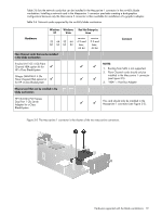
PCIe card cage, PCIe riser board, Disconnect these, connectors on the, PCIe/SAS cables
 |
View all HP Xw460c manuals
Add to My Manuals
Save this manual to your list of manuals |
Page 22 highlights
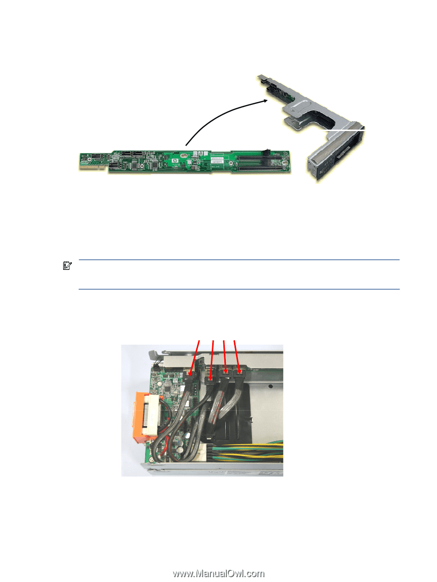
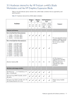
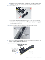
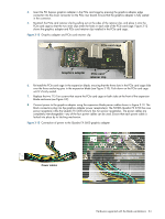
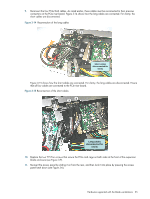
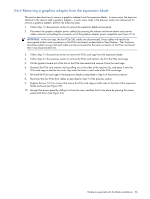
2. Next, the PCIe card cage is removed. The PCIe card cage, which houses the PCI Express graphics adapter, is shown in Figure 3-7. The PCIe card cage contains the PCIe riser board; the PCIe riser board contains an edge connector and two PCI Express connectors. Figure 3-7 PCIe card cage PCIe riser board PCIe card cage edge connector PCI Express connectors (only the lower connector is currently used) To remove the PCIe card cage, perform the following steps: a. Disconnect the four PCIe/SAS cables which connect from the blade workstation to the PCIe riser board (see Figure 3-8). Do not disconnect the ends of these cables which attach to the blade workstation through the hole in the bottom of the expansion blade. IMPORTANT: The four PCIe/SAS cables will need to be reconnected to their same connectors on the PCIe riser board, as described in Step 9. Their locations should be noted to ensure that each cable can be reconnected to the same connector on the PCIe riser board that it was disconnected from. Figure 3-8 Disconnect the four PCIe/SAS cables Disconnect these connectors on the PCIe/SAS cables The four PCIe/SAS cables are disconnected as follows: • Push each cable connector in towards its mating connector on the PCIe riser board to relieve any pressure on the latching mechanism. • Press the connector latch, and unplug the cable from its mating connector. Hardware supported with the blade workstations 22
-
 1
1 -
2
-
3
-
4
-
5
-
6
-
7
-
8
-
9
-
10
-
11
-
12
-
13
-
14
-
15
-
16
-
 17
17 -
 18
18 -
 19
19 -
 20
20 -
 21
21 -
 22
22 -
 23
23 -
 24
24 -
 25
25 -
 26
26 -
 27
27 -
28
-
29
-
30
-
31
-
32
-
33
-
34
-
35
 |
 |